PROFESSIONAL SERIES Remote Start Installation Guide CA 4050 2009 Audiovox Electronics Corporation. All rights reserved.
Before You Begin ...................................................................................... 3 Wire Connection Guide ........................................................................... 4 7 Pin Main Harness ................................................................................... 5 3 Pin Parking Light Harness ..................................................................... 7 6 Pin Start Harness .................................................................................
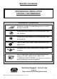
BEFORE YOU BEGIN PROFESSIONAL INSTALLATION STRONGLY RECOMMENDED Installation Precautions: Roll down window to avoid locking keys in vehicle during installation Avoid mounting components or routing wires near hot surfaces Avoid mounting components or routing wires near moving parts Tape or loom wires under hood for protection and appearance Use grommets when routing wires through metal surfaces Use a Digital Multi Meter for testing and verifying circuits.
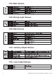
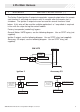
Pin Main Harness 3 Pin Parking Light Harness 6 Pin Start Harness 4 Pin Auxiliary Output Harness 2 Pin Lock Output Harness 4 2009 Audiovox Electronics Corporation. All rights reserved.
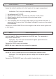
4 Pin Main Harness 1 BLUE/BLACK IGNITION 3 / ACTIVE OUTPUT ( - ) The Active Output/Ignition 3 output wire provides a ground output when the remote start function is activated and remains until 4 seconds after the remote start is shutdown. The Ignition 3 output wire can be used for several functions listed below. If this wire will be used for multiple application's a 1 amp diode is required in-line with the stripe facing the control module. Factory transponder (coded key) bypass.
2 PURPLE/WHITE TACH INPUT Locate the vehicle’s ignition coil or fuel injector in the engine compartment. Verification: Test using the following procedure: 1. 2. 3. 4. 5. Set voltmeter to AC VOLTS. Attach positive lead of a volt meter to a constant 12-volt source. Attach negative lead of a volt meter to the wire to be tested. Start the engine. Have someone press on the gas pedal slightly as you monitor the meter.
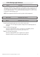
3 Pin Parking Light Harness 1 BLACK GROUND Connect the BLACK wire to a solid chassis ground point using a ring terminal and self tapping screw (not supplied). Scrape away paint from the grounding point to ensure a good connection. The recommended grounding point is a metal surface in the driver’s side kick panel area. NOTE: Do not ground the BLACK wire with any other vehicle components.
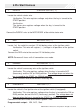
6 Pin Start Harness 1 PURPLE STARTER OUTPUT ( + ) Locate the vehicle starter wire. Verification: This wire registers voltage only when the key is turned to the START position. Verification: The starter wire registers voltage when the key is turned to the START position. Connect the PURPLE wire to the MOTOR SIDE of the vehicle starter wire. 2 RED BATTERY 12V ( + ) Locate 1 of the vehicle’s constant 12 Volt battery wires at the ignition switch.
5 RED BATTERY 12V ( + ) Locate 1 of the vehicle’s constant 12 Volt battery wires at the ignition switch. Verification: This wire will register ( + ) voltage in all positions of the ignition switch. Connect the RED wire to the constant 12 Volt battery wire. NOTE: Remove all fuses until all connections are made. 6 PINK IGNITION 1 ( + ) Locate the vehicle’s ignition wire at the ignition switch. Verification: This wire registers voltage when the key is turned to the ON (or RUN) position.
3 GREEN/WHITE FACTORY ARM / PULSE AFTER SHUTDOWN ( - ) This wire will supply a ( - ) 500mA pulse both upon arming the system and after the remote start shuts down. This is typically used to re-lock the vehicle’s doors if they unlock upon remote start shutdown. It can also be used to pulse a door pinswitch wire to prevent the vehicle’s accessories from remaining on after remote start shutdown.
Additional Ports Antenna Port Mount the supplied antenna/receiver to a clear spot on the vehicle's windshield that will not block the driver's vision. A good location is usually high on the windshield near the rear view mirror. Be careful not to mount the antenna/receiver on any metallic window film, as this will effect system range. Route the antenna/ receiver cable to the control module and plug into the antenna port.
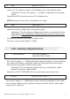
Set Up & Programming Transmitter Programming - Feature Bank 1 - 3 chirps 1. Turn the ignition ON. 2. Press and hold the valet/override button. 3. Within 10 seconds the system will chirp (3) three times. 4. Press 1 button of each transmitter you wish to program. 5. The system will respond with 1 light flash for each accepted transmitter. 6. Pressing the override button at anytime during programming will advance to the next bank.
Feature Bank 1 - 3 Chirps Transmitter Programming Refer to transmitter programming. Feature set not available on this model. 2009 Audiovox Electronics Corporation. All rights reserved.
Tach Programming The unit will not operate unless tach is programmed or tachless option is turned ON. If an attempt is made to start the vehicle via the remote start without first programming tach, the unit will flash the parking lights 7 times indicating tach has not been learned and stored. If the tach rate is not properly programmed to the specific vehicle, the unit may not realize that the vehicle is running in certain instances and reengage the starter motor.
Feature Bank 3 - Output Control 1 - Extended Lock Pulse: Controls the timing of the BLUE and GREEN lock output wires. 1 Second - Single 1 second unlock pulse. 3.5 Seconds - Single 3.5 second unlock pulse. Double Pulse Unlock - Double 1second unlock pulse. Feature Bank 4 - Remote Start Control 2 - Run Time: Controls the time in minutes that the vehicle will stay running under control of the remote start until the system times out.
5 - Voltage Level: The voltage variance for remote start when set to tachless. (see tach mode) HIGH - The variance in battery voltage from before the remote start is activated to after the engine is running must be greater than 0.5 volts. LOW - The variance in battery voltage from before the remote start is activated to after the engine is running may be less than 0.5 volts. 6 - Crank Time: Preset output times for the PURPLE starter wire. 1 Second 0.8 Seconds 1.
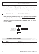
Transmitter Button Functions 1 Button Transmitter Start / Aux Unlock X Remote Start X Remote Start Shut Down X Operation Method Press and Hold - During remote start only Press and Release (1 or 2 times depending on selectable option) Press and Release (1 or 2 times depending on selectable option) Remote Start Shutdown Diagnostics If the remote start shuts down or fails to start, the parking lights will flash one of the patterns below indicating the shutdown input.
2009 Audiovox Electronics Corporation. All rights reserved.
2009 Audiovox Electronics Corporation. All rights reserved.
Audiovox Electronics Corporation. Customer Service 1-800-421-3209 WWW.CODE-ALARM.COM FCC COMPLIANCE This device complies with Part 15 of the FCC rules and with RSS-210 of Industry Canada. Operation is subject to the following two conditions: 1. This device may not cause harmful interference, and 2. This device must accept any interference received, including any interference that may cause undesired operation.