
Troubleshooting guide


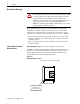
Table Of Contents

1336 PLUS II - 6.16 - June, 2001
Chapter
2
Control Logic Wiring and Adapters
Chapter Objectives
This chapter introduces you to terminal block locations and wiring and
adapter locations and functions.
Chapter Overview
This chapter illustrates and describes:
• Control Logic Interface Options L4, L5, L6, L7, L8 and L9 including
terminal block TB3.
• TB3 terminal designations.
• TB3 input mode selections and functions.
All printed circuit boards, except the Main Control Board assembly, are
referenced to negative ground (-bus).
!
ATTENTION:
Some printed circuit boards and drive
components may contain hazardous voltage levels. Remove and
lock out power before you disconnect or reconnect wires, and
before you remove or replace fuses and circuit boards. Verify bus
voltage by measuring the voltage between +DC and -DC on
Terminal Block TB1. Do not attempt to service the drive until the
bus voltage has discharged to zero volts.
ATTENTION:
This assembly contains parts and
sub-assemblies that are sensitive to electrostatic discharge. Static
control precautions are required when servicing this assembly.
Component damage may result if you ignore electrostatic
discharge control procedures. If you are not familiar with static
control procedures, reference Allen-Bradley Publication
8000-4.5.2, Guarding Against Electostatic Discharge, or any
other applicable ESD protection handbook.