
Troubleshooting guide


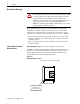
Table Of Contents

1336 PLUS - 6.16 - September, 2001
1-6 Introduction
Default
When a drive defaults, it automatically changes to a pre-programmed
setting.
Enable Input
The Enable Input is a terminal connection on the Control Interface Board.
This connection provides an external input to enable or disable the Drive
Output section. It must be true to permit the drive to operate.
False
False refers to a logical false state. For instance, a Control Interface signal
on TB3 is false when the input contact is open or the appropriate voltage is
not applied to the Control Interface Board.
Jumper
A jumper completes a circuit between two pins within a male connector on
a drive board. In the absence of certain optional equipment using female
connectors, jumpers are applied to certain pins within a male connector to
complete specific and necessary circuits.
Control Interface Board
A Control Interface Board plugs into connectors J2 & J4, located on the
lower portion of the Main Control Board. This board is identified as L4/4E,
L5/L5E, L6/L6E, L7E, L8E or L9E and provides optional control wiring
configurations for a drive Control Interface Board.
Parameter
Parameters are programmable drive functions that define various operating
functions or status displays of a drive. Refer to Bulletin 1336 PLUSII User
Manual (1336 PLUS-5.3) for Parameter details.
Press
Press a button on the Human Interface Module to change Parameter settings
and drive functions.
True
True refers to a logical true state. For example, a Control Interface signal on
TB3 is true when: L4/L4E contact input is closed, L8E input terminal
registers 24V, or L9E input terminal registers 115 VAC.