
Troubleshooting guide


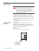
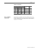
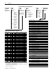
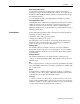
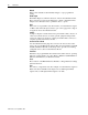
Table Of Contents
1336 PLUS - 6.16 - September, 2001
1-4 Introduction
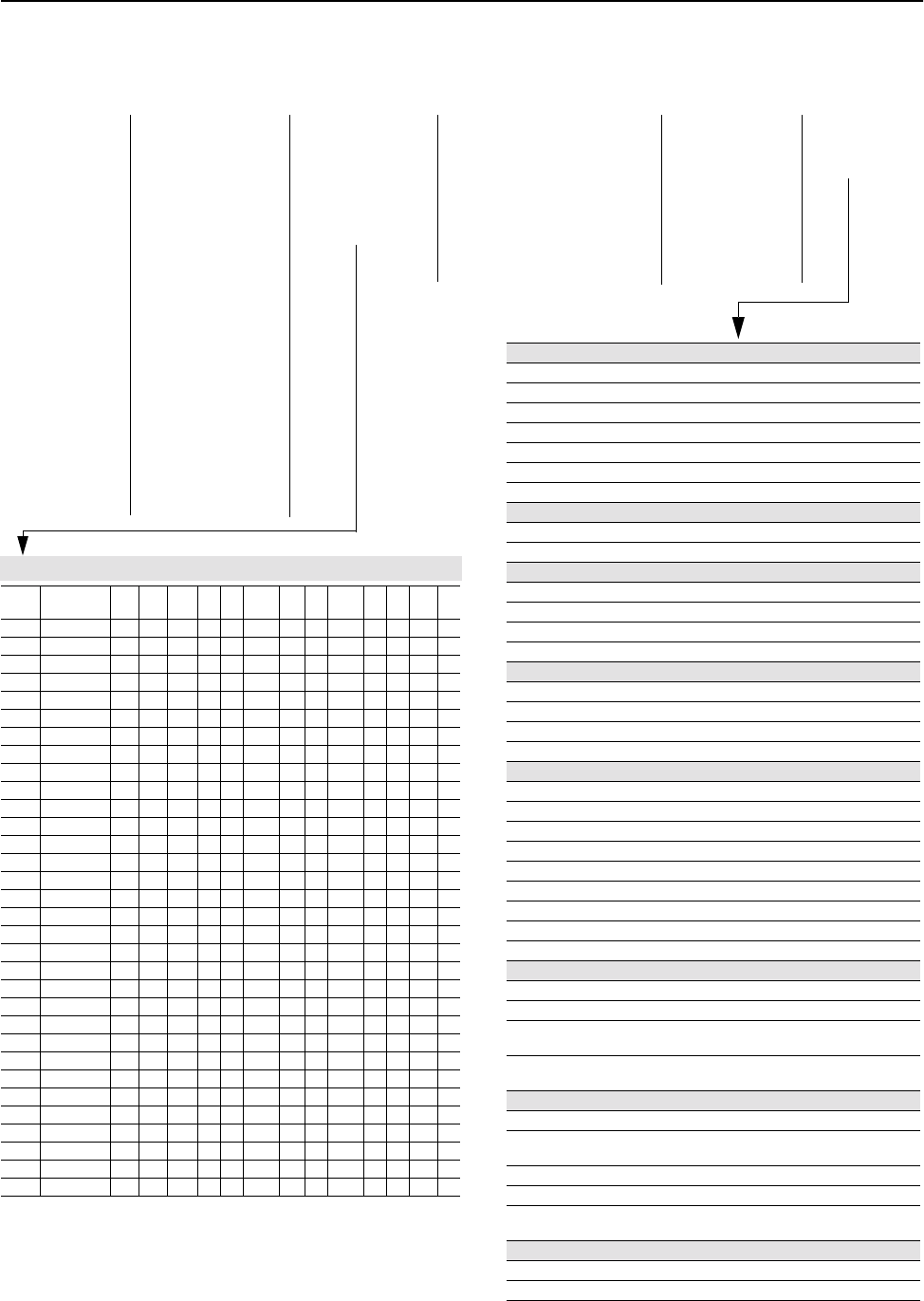
1336 PLUS II Drive Catalog Numbers
1336F
First Position
Bulletin Number
BR
Second Position
Vo lt ag e
Letter Voltages
AQ 200-240V AC or
310V DC
BR 380-480VAC or
513-620V DC
CW 500-600V AC or
775V DC
A 200-240V AC
B 380-480V AC
BP/BPR
➃
380-480V AC
(F Frame)
BX Special Rating
C 500-600V AC
CP/CPR
➃
500-600V AC
(F Frame)
Q 310V DC
R 513-620V DC
RX Special Rating
W 775V DC
F30
Third Position
Nominal HP Rating
Refer to table below for
ratings and possible
voltage combinations.
AA
Fourth Position
Enclosure Type
Code Type
AA IP 20 (NEMA 1)
AE IP 20 (NEMA 1)/EMC
AF IP 65 (NEMA 4)
➂
AJ IP 54 (NEMA 12)
➂
AN IP 00 (Open)
EN
Fifth Position
Language Group
➀
Code Language
EN English
FR French
DE German
IT Italian
ES Spanish
JP Japanese
MODS
Sixth Position
Options
Code Description
Human Interface Module, Snap-In, IP20 (NEMA Type 1)
HASB Snap-In Cradle/Blank Plate
HASP Programmer Only
HCSP Programmer Only & Upload/Download Capability
HAS1 Programmer/Controller w/Analog Pot
HCS1 Programmer/Controller w/Analog Pot & Upload/Download Capability
HAS2 Programmer/Controller w/Digital Pot
HCS2 Programmer/Controller w/Digital Pot & Upload/Download Capability
Human Interface Module, IP65/54 (NEMA Type 4/12)
HJP Programmer Only
HJ2 Programmer/Controller w/Digital Pot
Communication Options –- B Frame & Up (Adapter 6)
GM1 Single Point Remote I/O B Frame
GM2 RS-232/422/485, DF1 & DH485 B Frame
GM5 DeviceNet™
GM6 Enhanced DeviceNet™
Communication Options –- All Frames (Adapter 1)
GMS1 GM1 with Snap-In Cradle
GMS2 GM2 with Snap-In Cradle
GMS5 GM5 with Snap-In Cradle
GMS6 GM6 with Snap-In Cradle
Control Interface Options
L4 TTL Contact
L4E TTL Contact & Encoder Feedback
L7E TTL Contact & Encoder Fdbck. for use with Encoder Loss Detection
L5 24V AC/DC
L5E 24V AC/DC & Encoder Feedback
L8E 24V AC/DC & Encoder Feedback for use with Encoder Loss Detection
L6 115V AC
L6E 115V AC & Encoder Feedback
L9E 115V AC & Encoder Feedback for use with Encoder Loss Detection
Analog Interface Options – Slot A
• Choose No More than One – Configurable Inputs/Outputs are 10V or 20mA
LA2 Two Isolated Configurable Inputs
LA6 One Isolated Bi-polar Input (
±
10V or
±
20mA) and One Isolated
Thermistor Input
LA7 One Isolated Bi-polar Input (
±
10V or
±
20mA) and One Isolated
Configurable Input
Analog Interface Options – Slot B
• Choose No More than One – Configurable Inputs/Outputs are 10V or 20mA
LA1 Single-ended, Non-isolated Configurable (including Pot) Input & 2
Single-ended, Non-isolated Outputs (1 - Configurable, 1 - 20mA)
LA3 Two Isolated Configurable Outputs
LA4 One Isolated Configurable Input & Output
LA5 Isolated Pulse Input, Non-isolated Pulse Output & Single-ended,
Non-isolated Configurable Output
Common Mode Choke –- F & G Frame (must be specified for F Frame)
CM Internal Common Mode Choke (factory installed)
NCM No Common Mode Choke
➀
Language must be specified to ensure shipment of appropriate User Manual.
➁
G Frame Standard Drives in enclosed construction are supplied through the
Configured Drives Pro-
gram
and will have an "A" suffix after the HP rating.
➂
D through G Frame drives in IP 65 (NEMA Type 4) and IP 54 (NEMA Type 12) configurations are
supplied through the Configured Drives Program.
➃
"xPR" has a "roll=in" type chassis.
Voltage and Nominal HP Rating Combinations
Code Rating AQ BR CW A B
BP/
BPR BX C
CP/
CPR Q R RX W
F05 0.37 (0.5)
●●
F07 0.56 (0.75)
●●
F10 0.75 (1)
●●●
F15 1.2 (1.5)
●●
F20 1.5 (2)
●●●
F30 2.2 (3)
●●●
F50 3.7 (5)
●●●
F75 5.5 (7.5)
●●●
F100 7.5 (10)
●●
F150 11 (15)
●●
F200 15 (20)
●●
007 5.5 (7.5)
●●
010 7.5 (10)
●●
015 11 (15)
●● ●●
020 15 (20)
●● ●●
025 18.5 (25)
●● ● ●● ●
030 22 (30)
●● ● ●● ●
040 30 (40)
●● ● ● ●● ● ●
050 37 (50)
●● ● ●● ●
060 45 (60)
●● ● ● ●● ● ●
075 56 (75)
●● ● ●● ●
100 75 (100)
●● ● ●● ●
125 93 (125)
●● ● ●● ●
150 112 (150)
● ●● ●●●
200 149 (200)
●●●●
250 187 (250)
➁ ● ● ●● ●●●
300 224 (300)
➁●●●●●
350 261 (350)
➁●●●●●●
400 298 (400)
➁●●●●●●
450 336 (450)
➁●●●●●
500 373 (500)
➁●●●●
600 448 (600)
●●●●
–
–
–
–