
Troubleshooting guide
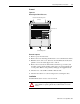
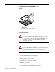
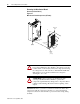
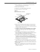
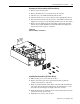

Table Of Contents
1336 PLUS - 6.16 - September, 2001
Disassembly and Access Procedures 4-9
Removing the Fan Assemblies (A4 Frame Drives)
1.
Remove power from the drive.
2.
Remove the Enclosure cover if the drive has an enclosure.
3.
Check for zero volts at TB1 Terminals +DC and -DC
4.
Check for the absence of control voltage before beginning fan removal.
5.
Disconnect the fan leads at the J2 connector on the Main Control Board
(Figure 4.6). Cut any tie wraps fastening the fan leads to the drive frame.
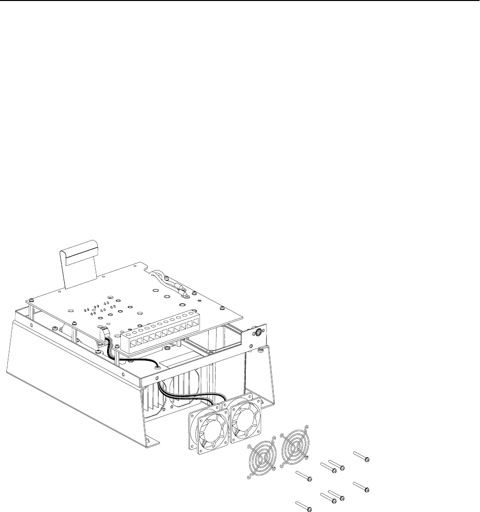
6.
Remove the four phillips head screws holding each fan unit and safety
shield to the heat sink. Withdraw each fan unit while threading the fan
leads down from the top layer of the drive.
Figure 4.6
Fan Assemblies
(A4 Frame).
Installing Fan Assemblies (A4 Frame Drives)
1.
Make certain power is removed from the drive.
2.
Begin to thread the leads on the replacement fan units up thru the
opening to the first layer of the drive.
3.
Position each fan unit with safety shield on the heat sink and install the
four screws thru the shields and the fans into the threaded holes on the
heat sink as shown in Figure 4.6. Tighten all screws securely.
4.
Install the fan leads at terminal J2 and reroute and fasten the leads in the
same location as the previous unit.
5.
Install all covers and re-power the drive.