
Troubleshooting guide
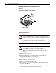
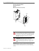
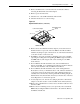
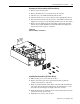

Table Of Contents

1336 PLUS - 6.16 - September, 2001
4-8 Disassembly and Access Procedures
Installing the Main Control Board
Installation (A Frame Drives)
1.
Position the Main Control Board on the standoffs and install the six
screws that were previously removed in step 11 of disassembly. Torque
screws to 26 in-lb (3 N-m).
2.
Install the HIM cradle to the Main Control Board with four screws.
3.
Reinstall the communications connector at J3, the ribbon cable at J1 and
all wires at TB2.
4.
Reinstall the Control Interface Board on the Main Control Board.
5.
Install the HIM in the HIM cradle.
NOTE: Verify that the Analog Option Board(s) are correctly installed in the
proper slot for your application. The terminal designations at TB2 change
based on the Analog Option board installed and on slot location. Refer to
Publication 1336 PLUS-5.70 if you have questions on Analog Option Board
installation and set up.
6.
Apply power - if a fault occurs, “Reset Defaults”. Download parameters
(if previously uploaded) from the HIM.
Gate Driver/Power Supply/Precharge Board
IMPORTANT: Individual components such as Bridge Rectifiers and
Transistor Modules cannot be tested or replaced separately as they are part
of the Gate Driver/Power Supply Board assembly.
If you suspect a problem on the Gate Driver/Power Supply Board, the Drive
should be returned to the factory for repair or replacement.