
Troubleshooting guide
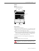
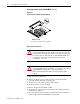
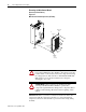
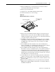
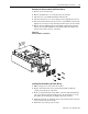
Table Of Contents
1336 PLUS - 6.16 - September, 2001
4-6 Disassembly and Access Procedures
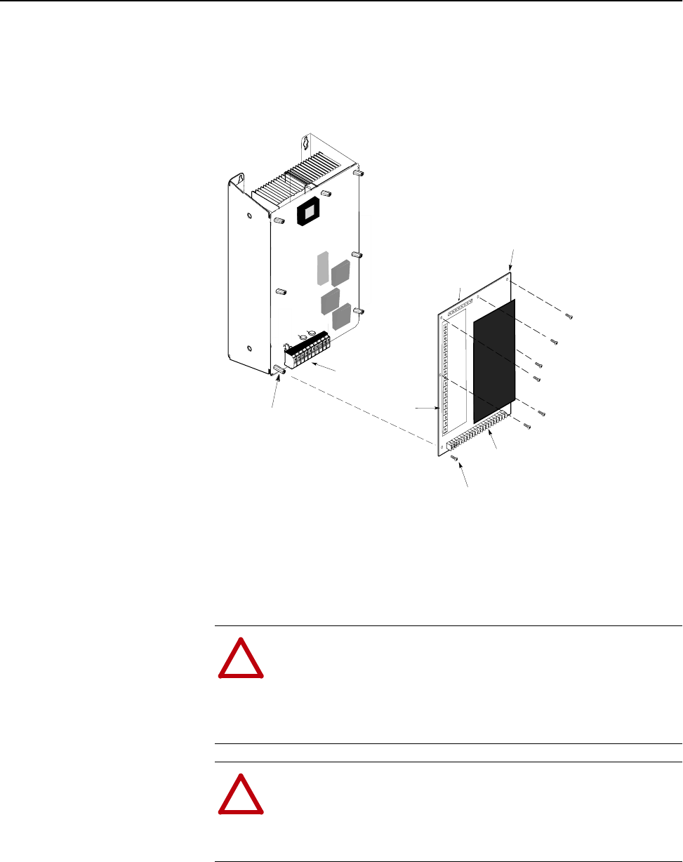
Removing the Main Control Board
Removal (A Frame Drives)
Figure 4.4
Main Control Board Components (A Frame)
.
IMPORTANT: Before you remove connections and wires from the drive
components, mark the connections and wires to correspond with their
component connections and terminals to prevent incorrect wiring during
assembly.
Stand-Of
Mounting
Screw
(7 Places)
Connector
J1
Terminal Strip
TB2
Terminal Strip
TB 1
Main Control
Board
(7 places)
Terminal Strip
TB 3
!
ATTENTION:
Disconnect and lock out power from the drive
before disassembling the drive. Failure to disconnect power may
result in death or serious injury. Verify bus voltage by measuring
the voltage between +DC and -DC on Terminal Block TB1.
Do
Not
attempt to service the drive until the bus voltage has
discharged to zero volts.
!
ATTENTION:
Wear a wrist-type grounding strap when
servicing 1336 PLUS II Drives. Failure to protect drive
components against ESD may damage drive components. Refer
to Electrostatic Discharge Precautions at the beginning of this
chapter.