
Troubleshooting guide
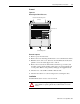
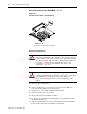
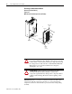

Table Of Contents
1336 PLUS - 6.16 - September, 2001
Disassembly and Access Procedures 4-3
Removal
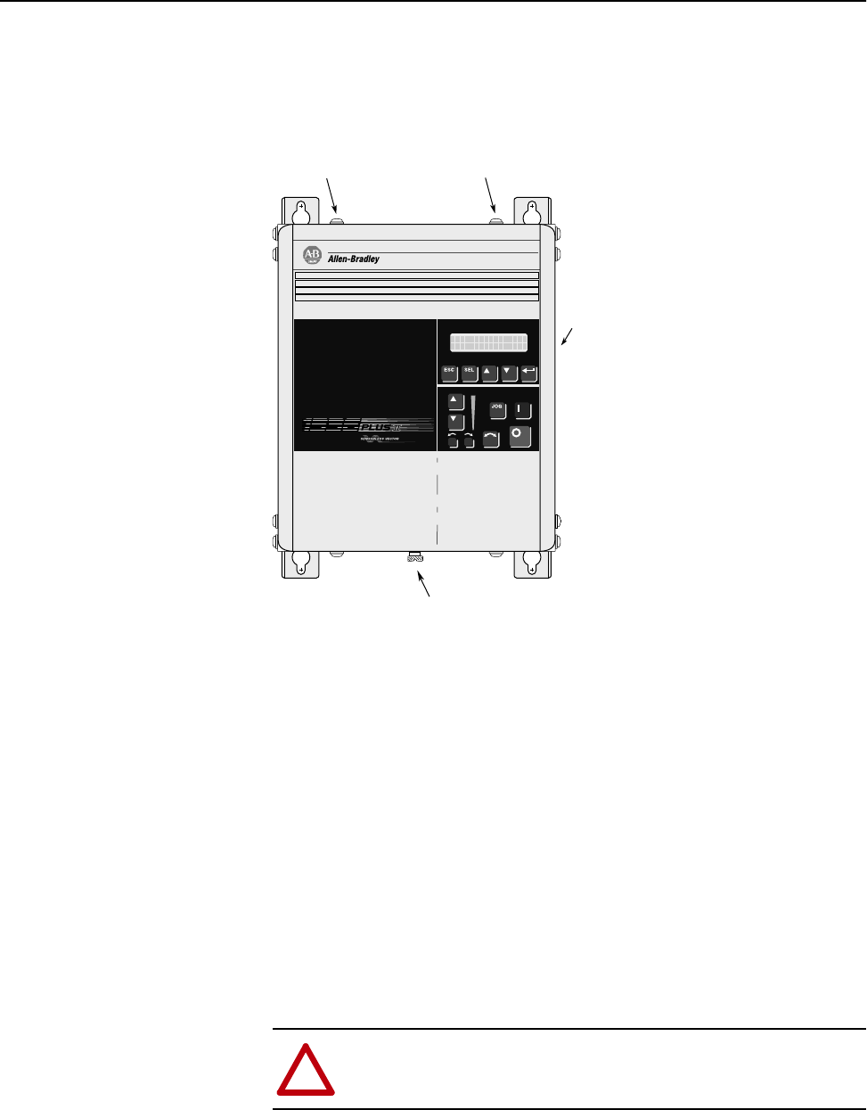
Figure 4.1
Removing the Drive Enclosure
.
Removal Sequence
1.
Remove power from the drive.
2.
Remove the screw fastening the Enclosure cover to the Enclosure frame.
3.
Pull the bottom of the cover outward to clear the Enclosure frame, then
pull the cover down off the upper slots to remove.
4.
Remove the four screws from the Enclosure frame top (2 screws) and
bottom(2 screws) panels and slide panels down out of engagement slots
on side panels. Remove side panels by sliding up off engagement tabs.
5.
Check for zero volts at TB1 terminals +DC and -DC.
6.
Check for the absence of control voltage before servicing the drive.
Installation
Install the Enclosure in reverse order of removal.
Enclosure Cover
Enclosure Frame Mounting Screws
(4 Places)
Cover Mounting Screw
!
ATTENTION:
Replace all guards before applying power to the
drive. Failure to replace guards may result in death or serious
injury!