
Troubleshooting guide
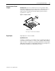

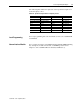
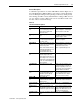
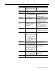
Table Of Contents

1336 PLUS II - 6.16 - September, 2001
Troubleshooting and Error Codes 3-3
Contact Description
A schematic representation of contacts CR1-CR4 is shown in Figure 2-5 of
the 1336 PLUS II User Manual. When powered these contacts will change
state. For Example: During normal operating conditions (no faults present,
drive running), the CR3 contacts (default firmware setting) at TB2-13 & 14
are open, and the contacts at TB2-14 & 15 are closed. When a fault occurs,
the state of these contacts will change.
Table 3.A
1336
PLUS
II
Fault Descriptions
Name & Fault # Description Action
Adptr Freq Err
65
The SCANport adapter that was
the selected frequency reference
sent a frequency greater than
32767 to the drive.
Correct the problem that is causing the
SCANport adapter to send the illegal
frequency reference to the drive.
Auxiliary Fault
02
The auxiliary input interlock is
open.
If Control Interface option is installed,
check TB3 connections. If not installed,
set [Input Mode] to “Status.”
Bgnd 10ms Over
51
Microprocessor loop fault. Occurs if
the 10ms background task hasn’t
been run in 15 ms.
Replace Main Control Board or com-
plete drive as required.
Bipolar Dir Flt
16
3 Wire – Bi-polar input is the active
frequency reference and direction
control is not possible.
2 Wire – Run Forward or Reverse
commands attempt direction con-
trol, but bi-polar input is not
masked from direction control.
a) Mask out direction control at bit 7 of
[Direction Mask]. b) Remove or mask
other direction control sources.
Set bit 7 of [Direction Mask] to zero.
Blwn Fuse Flt
58
If the difference between the com-
manded voltage and the mea-
sured voltage is greater than 1/8 of
rated voltage for 0.5 seconds, then
a fault will be issued indicating that
the bus fuse in 30 kW (40HP) & up
drives has blown.
Locate cause, replace fuse.
C167 Watchdog
17
Internal microprocessor fault. If there is only one occurrence, reset
the fault and continue. If the fault con-
tinuously or frequently reoccurs, con-
tact your local service representative or
replace the Main Control Board.
Diag C Lim Flt
36
The drive output current has
exceeded the hardware current
limit and the [Cur Lim Trip En]
parameter was enabled.
Check [Cur Lim Trip En]. Check for
excess load, improper DC boost set-
ting, DC brake volts set too high or
other causes of excess current.
Drive -> HIM Refer to Table 3B.
DSP Checksum
37
There was a breakdown in commu-
nications between the DSP and
main processors.
Reset to factory defaults. Replace Main
Control Board or Gate Driver Board.
DSP Comm Fault
27
Refer to the “Description” and “Action” statements for C167 Watchdog (F17)
above.
DSP Protected
46
Flash download included a new
DSP Main Block and J14 was not
installed when power was restored.
Remove power from the drive. Install
J14 per download kit instructions and
reapply power. When transfer is com-
plete, remove power and J14.
DSP Queue Fault
31
Refer to the “Description” and “Action” statements for C167 Watchdog (F17)
above.