
Troubleshooting guide


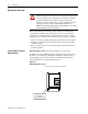
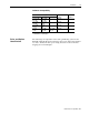
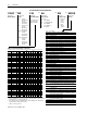
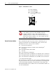
Table Of Contents
1336 PLUS - 6.16 - September, 2001
2-2 Control Logic Wiring and Adapters
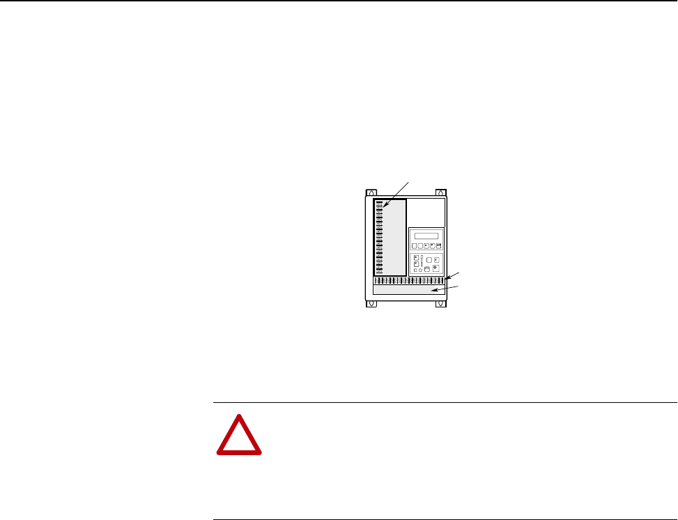
Figure 2.1 Terminal Block Locations
Control Interface Option
The Control Interface Option provides a means of interfacing various
signals and commands to the 1336 PLUS II by using contact closures.
Nine different versions of the option are available:
L4 Contact Closure Interface
1
L4E Contact Closure Interface with Encoder Feedback Inputs
1
L5 24V AC/DC
L5E 24V AC/DC & Encoder Feedback
L6 115V AC
L6E 115V AC & Encoder Feedback
L7E TTL Contact & Encoder Fdback for use with Encoder Loss Detection
L8E 24V AC/DC & Encoder Fdback for use with Encoder Loss Detection
L9E 115V AC & Encoder Feedback for use with Encoder Loss Detection
1
Uses internal +5V DC supply.
The user inputs are connected to the option board through TB3. The L4 thru
L9 options each have nine control options. The function of each input must
be selected through programming as explained later in this chapter. The
L4E, L5E and L6E options are similar to L4, L5 and L6 with the addition of
encoder feedback inputs.
!
ATTENTION:
The National Electrical Code (NEC) and local
codes outline provisions for safely installing electrical
equipment. Installation must comply with specifications
regarding wire types, conductor sizes, branch circuit protection
and disconnect devices. Failure to do so may result in personal
injury and/or equipment damage.
TB3
TB1
TB2
Power Terminal Block
Control & Signal Wiring
Control Interface Option
Control & Signal Shield Terminals
TB1
TB2
TB3
TE
Frames A1-A4
TB1
Control Interface
Option