336 PLUS II Adjustable Frequency AC Drive AQF05 - AQF75 BRF05 - BRF200 CWF10, CWF20 - CWF200 Troubleshooting Guide
Important User Information Solid state equipment has operational characteristics differing from those of electromechanical equipment. “Safety Guidelines for the Application, Installation and Maintenance of Solid State Controls” (Publication SGI-1.1 available from your local Allen-Bradley Sales Office or online at http:// www.ab.com/manuals/gi) describes some important differences between solid state equipment and hard-wired electromechanical devices.
Chapter 1 Introduction Manual Objectives This document is intended as a supplementary addition to the 1336 PLUS 6.1 Troubleshooting Guide. This supplement covers the additional information you will need to help troubleshoot or repair an Allen-Bradley Bulletin 1336 PLUS II Adjustable Frequency AC Drive with A1 - A4 Frames. Who Should Use This Manual This manual is intended for qualified service personnel responsible for troubleshooting and repairing the 1336 PLUS II Adjustable Frequency AC Drive.
1-2 Introduction Electrostatic Discharge ! ATTENTION: This assembly contains parts and sub-assemblies that are sensitive to electrostatic discharge. Static control precautions are required when servicing this assembly. Component damage may result if you ignore electrostatic discharge control procedures. If you are not familiar with static control procedures, reference Allen-Bradley Publication 8000-4.5.2, Guarding Against Electrostatic Damage, or any other applicable ESD protection handbook.
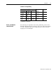
Introduction 1-3 Software Compatibility Three-Phase Drive Rating 1 200-240V 0.37-0.75 kW 0.5-1 HP 1.2-1.5 kW 1.5-2 HP 2.2-3.7 kW 3-5 HP 5.5 kW 7.5 HP 380-480V 0.37-1.2 kW 0.5-1.5 HP 1.5-2.2 kW 2-3 HP 3.7 kW 5 HP 5.5-15 kW 7.5-20 HP 500-600V – Compatible with Version . . . 1.0 & Up Frame Reference A1 – 1.0 & Up A2 – 1.0 & Up A3 0.75-15 kW 1-20 HP 1.0 & Up A4 1 kW and HP are constant torque.
1-4 Introduction 1336 PLUS II Drive Catalog Numbers 1336F – BR F30 First Position Second Position Third Position Fourth Position Fifth Position Sixth Position Bulletin Number Voltage Nominal HP Rating Enclosure Type Language Group ➀ Options Code Type Code Language AA IP 20 (NEMA 1) AE IP 20 (NEMA 1)/EMC AF IP 65 (NEMA 4) ➂ AJ IP 54 (NEMA 12) ➂ AN IP 00 (Open) EN FR DE IT ES JP Letter Voltages AQ 200-240V AC or 310V DC BR 380-480VAC or 513-620V DC CW 500-600V AC or 775V DC A
Introduction 1-5 Drive Rating Qualifications Several factors can affect drive rating. If more than one factor exists, derating percentages must be multiplied. For example, if a 14-amp drive is installed at a 2km (6,600 ft.) altitude and has a 2% high-input line voltage, the actual amp rating is: 14 x 94% altitude derating x 96% high-input line derating = 12.6 amps.
1-6 Introduction Default When a drive defaults, it automatically changes to a pre-programmed setting. Enable Input The Enable Input is a terminal connection on the Control Interface Board. This connection provides an external input to enable or disable the Drive Output section. It must be true to permit the drive to operate. False False refers to a logical false state.
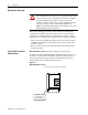
Chapter 2 Control Logic Wiring and Adapters Chapter Objectives This chapter introduces you to terminal block locations and wiring and adapter locations and functions. Chapter Overview This chapter illustrates and describes: • Control Logic Interface Options L4, L5, L6, L7, L8 and L9 including terminal block TB3. • TB3 terminal designations. • TB3 input mode selections and functions. All printed circuit boards, except the Main Control Board assembly, are referenced to negative ground (-bus).
2-2 Control Logic Wiring and Adapters Figure 2.1 Terminal Block Locations TB1 TB2 TB3 TE Power Terminal Block Control & Signal Wiring Control Interface Option Control & Signal Shield Terminals Control Interface Option TB3 TB1 TB2 TB1 Frames A1-A4 ! Control Interface Option ATTENTION: The National Electrical Code (NEC) and local codes outline provisions for safely installing electrical equipment.
Control Logic Wiring and Adapters Control Interface Board Jumpers 2-3 IMPORTANT: If the Control Interface Board is being installed, Main Control Board Jumpers at pins 3 & 4 and 17 & 18 of J2 must be removed and the proper [Input Mode] selected. If this board is removed, these jumpers must be reinstalled and the [Input Mode] parameter must be programmed to “Status (1).” Figure 2.
2-4 Control Logic Wiring and Adapters Figure 2.3 Digital I/O Default Settings - TB3.
Control Logic Wiring and Adapters 2-5 The following table defines the input state of the Speed Select inputs for a desired frequency source. Table 2.A Speed Select Input State vs. Frequency Source.
2-6 Control Logic Wiring and Adapters This Page Intentionally Blank 1336 PLUS - 6.
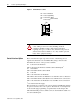
Chapter 3 Troubleshooting and Error Codes Chapter Objectives This chapter helps you trace faults to field-replaceable components. NOTE: On 1336 PLUS II A1 - A4 Frames, the only replaceable parts are the Main Control Board and Fans. Troubleshooting Overview To troubleshoot a 1336 PLUS II Adjustable Frequency AC Drive, you need a Range DVM, or VOM with a range capacity of at least 1000V.
3-2 Troubleshooting and Error Codes ! ATTENTION: This assembly contains parts and sub-assemblies that are sensitive to electrostatic discharge. Static control precautions are required when servicing this assembly. Component damage may result if you ignore electrostatic discharge control procedures. If you are not familiar with static control procedures, reference Allen-Bradley Publication 8000-4.5.2, Guarding Against Electrostatic Discharge, or any other applicable ESD protection handbook.
Troubleshooting and Error Codes 3-3 Contact Description A schematic representation of contacts CR1-CR4 is shown in Figure 2-5 of the 1336 PLUS II User Manual. When powered these contacts will change state. For Example: During normal operating conditions (no faults present, drive running), the CR3 contacts (default firmware setting) at TB2-13 & 14 are open, and the contacts at TB2-14 & 15 are closed. When a fault occurs, the state of these contacts will change. Table 3.
3-4 Troubleshooting and Error Codes Name & Fault # DSP Reset Fault 22 DSP Timeout Fault 28 EE Init Read 53 EE Init Value 54 EEprom Checksum 66 EEprom Fault 32 Encoder Loss 60 Fgnd 10ms Over 52 Ground Fault 13 Ground Warning 57 Hardware Trap 18 Description Action Power-up has been attempted with Check/verify wiring and contact operaan Open Stop contact or Closed tion. Start contact. Refer to the “Description” and “Action” statements for C167 Watchdog (F17) on page 3.3. 1. Gate Drive Bd.
Troubleshooting and Error Codes Name & Fault # Hertz Err Fault 29 Hertz Sel Fault 30 HIM -> Drive Ill Prog Input 62 Input Phase Flt 49 Load Loss Flt 20 Loop Overrn Flt 23 Max Retries Fault 33 Motor Mode Flt 24 Motor Stall Fault 06 Motor Thermistor 15 1336 PLUS II - 6.16 - September, 2001 Description This fault indicates that there is not a valid operating frequency. It can be caused by any of the following: 1. [Maximum Freq] is less than [Minimum Freq]. 2.
3-6 Troubleshooting and Error Codes Name & Fault # Mult Prog Input 61 Neg Slope Fault 35 Open Pot Fault 09 Op Error Fault 11 Option Error 14 Overcurrent Flt 12 Description A single source input function such as Reverse/Forward (open=1st function, closed=2nd function) has been programmed to more than one input or more than one “Run Reverse” input. Drive software detected a portion of the volts/hertz curve with a negative slope. An external pot is connected and the common side of the pot is open.
Troubleshooting and Error Codes Name & Fault # Phase W Fault 40 Poles Calc Flt 50 Power Loss Fault 03 Power Mode Fault 26 Power Overload 64 Precharge Fault 19 Precharge Open 56 Prm Access Flt 34 Reprogram Fault 48 ROM or RAM Flt 68 1336 PLUS II - 6.16 - September, 2001 Description A phase to ground fault has been detected between the drive and motor in this phase. Generated if the calculated value of [Motor Poles] is less than 2 or greater than 32.
3-8 Troubleshooting and Error Codes Name & Fault # Serial Fault 10 Shear Pin Fault 63 Sync Loss Fault 67 Temp Sense Open 55 Undervolt Fault 04 UV Short Fault 41 UW Short Fault 42 VW Short Fault 43 Description Action A SCANport adapter has been dis- 1. If no adapter was intentionally disconnected, check wiring to the connected and the [Logic Mask] bit SCANport adapters. Replace wiring, for that adapter is set to “1.” SCANport expander, SCANport adapters, Main Control Board or complete drive as required.
Troubleshooting and Error Codes 3-9 Table 3.B HIM Upload/Download Errors Fault Name HIM -> Drive Error Displayed Probable Cause ERROR 1 The HIM calculated a checksum for the file to be downloaded, then checked the EEPROM checksum of the download. The checksums did not match, indicating the file stored in the HIM is invalid and the download was not successful. ERROR 2 The number of parameters in the HIM file is different than the number of parameters in the drive file.
3-10 Troubleshooting and Error Codes Table 3.
Troubleshooting and Error Codes Diagnostic Procedures by Symptom These charts list drive symptoms, symptom descriptions, and recommended actions to remedy the symptoms.
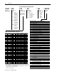
3-12 Troubleshooting and Error Codes No Display No HIM display Is the HIM backlight lit? Yes No Is the drive’s fan running? No Replace the HIM, Main Control Board, or Complete Drive as needed. Voltage present at TB1-R, -S, -T? Yes HIM connected properly? Yes Replace HIM, Main Control Board, or Complete Drive as needed No Restore incoming power to drive. Yes No Re-connect HIM. DC bus voltage present? Yes Replace Complete Drive No Replace Complete Drive 1336 PLUS - 6.
Troubleshooting and Error Codes 3-13 Drive Will Not Jog Local Human Interface Module used to control drive. Jog is not active if a START command is present. START command always overrides a JOG command. Drive will not Jog. Is drive running? Yes No No Will drive run if commanded to Start? Drive must be stopped before attempting to Jog Refer to “Drive Will Not Start”.
3-14 Troubleshooting and Error Codes Drive Stays at Zero Hertz When Started IMPORTANT: [Command Frequency] parameter in the Metering Group can be checked using the HIM. Drive stays at Zero Hertz when Started {Drive Status] Running Bit (Bit1) = 1? No Refer to “Drive Will Not Start”.
Chapter 4 Disassembly and Access Procedures Chapter Objectives This chapter describes general disassembly procedures required to remove the Control Interface Board and Main Control Board on A1 to A4 frame drives. Fan replacement is also detailed for A4 frame drives. Disassembly and Access Overview ! ATTENTION: Some printed circuit boards and drive components may contain hazardous voltage levels.
4-2 Disassembly and Access Procedures Tools You need the following tools to disassemble and assemble the drive: • • • • Disassembly and Access Procedures Pliers #2 Phillips and a magnetic flat blade screwdriver 5/16 - inch or 8mm socket. Torque wrench, metered in lb-in. or N-m Drive Enclosure Removal & Installation ! ! 1336 PLUS - 6.16 - September, 2001 ATTENTION: Disconnect and lock out power from the drive before disassembling the drive.
Disassembly and Access Procedures 4-3 Removal Figure 4.1 Removing the Drive Enclosure . Enclosure Frame Mounting Screws (4 Places) Enclosure Cover Cover Mounting Screw Removal Sequence 1. Remove power from the drive. 2. Remove the screw fastening the Enclosure cover to the Enclosure frame. 3. Pull the bottom of the cover outward to clear the Enclosure frame, then pull the cover down off the upper slots to remove. 4.
4-4 Disassembly and Access Procedures Removing Control Interface Board MOD - L4 - L9 Figure 4.2 Control Interface Board. (A Frame Drives) J2 3 J1 L E S 1 J1 C S E J8 G JO Frames1 A1 - A4 1 Refer to page 1–1 for frame reference classifications. Removal (A Frame Drives) ! ! ATTENTION: Disconnect and lock out power from the drive before disassembling the drive. Failure to disconnect power may result in death or serious injury.
Disassembly and Access Procedures 4-5 Installation 1. Position the Control Interface Board over the J2 and J4 connectors with the Terminal Block TB3 oriented on the left side of the drive with the drive facing up. 2. Push the Control Interface Board straight down onto the J2 & J4 connectors. Tighten the two captive screws holding the Interface Board to the Main Control Board. 3. Reinstall all wires previously removed at TB3. 4. Reinstall the enclosure cover before re-applying power to the drive.
4-6 Disassembly and Access Procedures Removing the Main Control Board Removal (A Frame Drives) Figure 4.4 Main Control Board Components (A Frame). Main Control Board Connector J1 Terminal Strip TB 1 Stand-Of Terminal Strip TB 3 (7 places) Terminal Strip TB2 Mounting Screw (7 Places) ! ! ATTENTION: Disconnect and lock out power from the drive before disassembling the drive. Failure to disconnect power may result in death or serious injury.
Disassembly and Access Procedures 4-7 1. Remove the Enclosure cover if the drive has an enclosure. Refer to removing the Drive Enclosure in this chapter. 2. Remove power from the drive. 3. Check for zero volts at TB1 Terminals +DC and -DC 4. Check for the absence of control voltage. Figure 4.5 Option Board Locations.
4-8 Disassembly and Access Procedures Installing the Main Control Board Installation (A Frame Drives) 1. Position the Main Control Board on the standoffs and install the six screws that were previously removed in step 11 of disassembly. Torque screws to 26 in-lb (3 N-m). 2. Install the HIM cradle to the Main Control Board with four screws. 3. Reinstall the communications connector at J3, the ribbon cable at J1 and all wires at TB2. 4. Reinstall the Control Interface Board on the Main Control Board. 5.
Disassembly and Access Procedures 4-9 Removing the Fan Assemblies (A4 Frame Drives) 1. 2. 3. 4. 5. Remove power from the drive. Remove the Enclosure cover if the drive has an enclosure. Check for zero volts at TB1 Terminals +DC and -DC Check for the absence of control voltage before beginning fan removal. Disconnect the fan leads at the J2 connector on the Main Control Board (Figure 4.6). Cut any tie wraps fastening the fan leads to the drive frame. 6.
4-10 Disassembly and Access Procedures 1336 PLUS - 6.
To contact Drives Technical Support . . . Tel: (1) 262 512-8176, Fax: (1) 262 512-2222 Email: support@drives.ra.rockwell.com, Online: www.ab.com/support/abdrives Publication 1336 PLUS 6.16 – September, 2001 P/N 188749 (01) Copyright 2001 Rockwell International Corporation. All rights reserved.