
Technical data


13.4
SUPPLEMENTARY BEAMS
GR2_60»65
13.4 Controls to stabilize the vehicle
(!) ATTENTION (!)
When controlling from the opposite side of the vehicle (it is not possible
visually to check the operation) it is compulsory make sure that no one
is or transits in close proximity to the outriggers.
- Manual extension of the outrigger supports: See Paragraph 13.2 or 13.3.
Note: When the outrigger ram is placed in a vertical or inclined position it
is necessary to position it in a working position during the extension of the
support.
- Outrigger ram descent: position the lever CD on the corresponding position
and then, activate the lever C.
(!) ATTENTION (!)
During the stabilising operations, for each outrigger ram, it is recommen-
ded to DESCENT the outrigger as the last manoeuvre.
(!) ATTENTION (!)
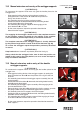
The complete extension of the outrigger supports is visually indicated by
the yellow triangles which are found at the end of the beam (and of the
support if it’s supplied with extra double extension beams). (Fig. 8b).
The stabilization has to be carried out with care and gradually keeping
the vehicle in horizontal levelled condition to prevent springs overloads
and chassis torsions.
Manoeuvres for re-entry of the crane outriggers and supplemen-
tary outriggers within the overall vehicle width after crane use.
Repeat by inverting the sequence of the operations.
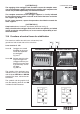
(!) ATTENTION (!)
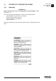
Keep hands clear of automatic stop device (lever A of the fig. 8c).
(!) Always check that the outrigger supports, once in their rest
position, are locked in their seat by the safety devices, so as
to assure the impossibility of accidental movement. (Fig. 8c).
fig. 8c
A