
Technical data


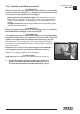


(!) ATTENTION (!)
The engaging of the outriggers lock B and B1 ensures the complete exten-
sion of the outrigger support (essential for the stability of the complete crane
vehicle unit) and the impossibility of accidental movement.
(!) ATTENTION (!)
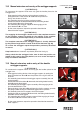
The complete extension of the outrigger supports is visually indicated
by the yellow triangles which are found at the end of the beam and of the
first support (fig. 8b-9b)
By the same sequence, repeat the operations described to extend the
other supports.
(!) ATTENTION (!)
Keep hands clear of automatic stop device (lever A of the fig. 9).
Always check that the outriggers locks, once in their rest position, are locked
in their seat by the safety devices, so as to assure the impossibility of acci-
dental movement.
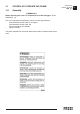
13.4 Functions of control levers for stabilization
The controls to stabilize the vehicle are activated only from
ground level and on both sides of the crane base.
Lever function
C - CD
Levers
C Outrigger rams control
distributor for the crane
and for the supplemen-
tary outriggers.
Fig. 10-11
Levers
CD
Deviator control for selec-
ting the outrigger rams
(outrigger-extension); the
position of the select lever
is guaranteed by an inter-
nal detent.
Fig. 10b-11b
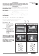
The controls of the outrigger rams,
indicated in the fig. 10a-11a coincide
with the plates DE3706 and DE3705
placed on the base, next to the con-
trol stations.
The symbols and the graphics indi-
cate the operating levers C and CD
in relation to their movement.
13.4
SUPPLEMENTARY BEAMS
GR2_60»65
fig. 11a
fig. 11
C
fig. 11b
CD
DOUBLE CONTROL SIDE
fig. 10a
fig. 10
C
fig. 10b
CD
DISTRIBUTOR SIDE