FASSI CRANE F 65A.22 use and maintenance FROM SERIAL NUMBER *5001* INDEX 1 INTRODUCTION 2 2.1 2.2 2.3 CLASSIFICATION OF THE CRANE MODEL Generality Hydraulic jibs (not available) Technical data 3 3.1 3.2 3.3 CAPACITY PLATES Generality Capacity plates with lifting moment limiting device (optional) Capacity plates with load limiting device 4 4.
13.4 13.5 Functions of control levers for stabilization Controls to stabilize the vehicle 14 14.1 14.2 14.3 14.4 14.5 14.6 14.
FASSI CRANE use and maintenance ORIGINAL INSTRUCTIONS THANK YOU FOR SELECTING ONE OF FASSI CRANES. This crane is the result of FASSI philosophy: ongoing research, rigorous testing, data verification, and analysis of performances. Many years of experience has allowed us to grant you the maximum safety of operation together with the optimization of machine performances. All this represents the core of FASSI quality system.
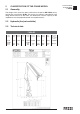
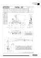
2 CLASSIFICATION OF THE CRANE MODEL 2.1 CLASSIFICATION OF THE CRANE MODEL F 65A.22 Generality The design of this crane has been carried out in respect of DIN 15018 norms, fatigue test classification H1B3. The crane can operate, intermittently, with lifting devices other than the hook. The dimensions and the capacity of the implements must be proportioned with crane performances. 2.2 Hydraulic jibs (not available) 2.3 Technical data F 65A.
CLASSIFICATION OF THE CRANE MODEL F 65A.22 2.
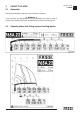
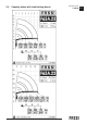
3 CAPACITY PLATES 3.1 Generality The represented plates refer to the nominal design capacities. (!) WARNING (!) If the capacities are downgraded or partially reduced (e.g. sector in front of vehicle cab) capacity plates must be applied in line with the final test figures. 3.2 Capacity plates with lifting moment limiting device CAPACITY PLATES F 65A.
CAPACITY PLATES F 65A.22 3.
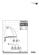
3.3 Capacity plates with load limiting device CAPACITY PLATES F 65A.22 3.
CAPACITY PLATES F 65A.22 3.
4 HYDRAULIC SCHEMATICS (if fitted) Hydraulic schematic for crane - HCD3M distributor - ground controls - “electronic” lifting moment limiting device - CE CODE DESCRIPTION DV003 EV128 EV117 FI870 M1/M2 PR103 RU975 TR002 DEVIATOR ELECTROVALVE ELECTROVALVE FILTER (RETURN) GAUGE QUICK CONNECTION PRESSURE SWITCH FAUCET PRESSURE TRANSDUCER VA164 VA185 VA268 VA270 VA215 VA217 VA239 VA258 DOUBLE EFFECT BLOCK VALVE SELECTOR VALVE DOUBLE EFFECT BLOCK VALVE SIMPLE EFFECT BLOCK VALVE OIL FLOW CHECK VALVE SEQUEN
Hydraulic schematic for crane - Danfoss S800 distributor - “electronic” lifting moment limiting device - CE CODE DESCRIPTION DV003 EV124 FI781 FI870 M1/M2 PR103 RU975 RU978 TR002 VA148 DEVIATOR ELECTROVALVE FILTER (HIGH PRESSURE) FILTER (RETURN) GAUGE QUICK CONNECTION PRESSURE SWITCH FAUCET FAUCET PRESSURE TRANSDUCER MAIN PRESSURE VALVE WITH ELECTRIC ACTIVATION VA164 VA185 VA200 VA213 VA215 VA227 VA232 VA239 VA257 VA258 DOUBLE EFFECT BLOCK VALVE SELECTOR VALVE DOUBLE EFFECT BLOCK VALVE SIMPLE EFFECT B
Hydraulic schematic for crane - HCD3M distributor - ground controls - lifting moment limiting device "intelligent type" HO - CE SIMBOLO DESCRIZIONE DV003 DV012 EV132 FI870 M1/M2 RU975 VA164 DEVIATORE PULSANTE A FUNGO ELETTROVALVOLA FILTRO DI RITORNO PRESA MANOMETRICA RUBINETTO A SFERA VALVOLA DI BLOCCO DOPPIA VA215 VA239 VA258 VA268 VA270 VA284 VA285 VALVOLA REGOLATRICE DI PORTATA VALVOLA DI BLOCCO SEMPLICE VALVOLA DI SEQUENZA VALVOLA DI BLOCCO DOPPIA VALVOLA DI BLOCCO SEMPLICE VALVOLA LIMITATRICE VAL
4.1 HYDRAULIC SCHEMATICS (version with load limiting device) Hydraulic schematic for crane - HCD3M distributor - ground controls - load limiting device - ExtraCE CODE DESCRIPTION DV003 FI870 PR103 RU975 VA164 VA200 DEVIATOR OIL FILTER (RETURN) PRESSURE SWITCH FAUCET DOUBLE EFFECT BLOCK VALVE DOUBLE EFFECT BLOCK VALVE VA213 VA215 VA239 SIMPLE EFFECT BLOCK VALVE OIL FLOW CHECK VALVE SIMPLE EFFECT BLOCK VALVE HYDRAULIC SCHEMATICS GR2_65 4.
Hydraulic schematic for crane - Danfoss S800 distributor - load limiting device - ExtraCE CODE DESCRIPTION DV003 FI870 RU975 VA102 VA200 VA213 DEVIATOR OIL FILTER (RETURN) FAUCET DOUBLE EFFECT BLOCK VALVE DOUBLE EFFECT BLOCK VALVE SIMPLE EFFECT BLOCK VALVE VA215 VA227 VA239 VA257 OIL FLOW CHECK VALVE SEQUENCE VALVE SIMPLE EFFECT BLOCK VALVE SEQUENCE VALVE HYDRAULIC SCHEMATICS GR2_65 4.
5 ELECTRIC SCHEMATICS ELECTRIC SCHEMATICS GR2_45»65_3_4_SE 5 Electric schematic for crane N° DESCRIPTION ALIM EV1 EV2 EV3 LP IP1/2/3 LCV LR M1 M2 M3 M4 M5 M6 M7 MS MV2 P1 UCF S1/2/3/… SAT1 SAT2 SD1 TP1 TP2 TP3 ELECTRICAL FEED CABLE MAIN CONTROL PANEL ELECTROVALVE FOR CRANE BLOCK ELECTROVALVE FOR LIFTING MOMENT LIMITING DEVICE OF THE TWO WORKING ZONES XP ELECTROVALVE FLASHING PROXIMITY MICROSWITCH FOR ROTATION CONTROL WINCH LOAD LIMITING DEVICE ACTIVATION OF OVERLOAD BLOCK RED WARNING LIGHT MICROSWI
6 SAFETY NORMS SAFETY NORMS GR2_3_4_5 Strictly conform to the norms reported by the plates DE2499B (fig. 1) or DE4236 (fig. 1a) placed next to the controls, in order to avoid possible accidents while operating the crane. Only authorized persons are allowed to operate the crane. The crane must be used on firm, level ground. Check that the vehicle hand brake is on and that the wheels are chocked.
7 WARNING AND INSTRUCTIONS 7.1 Generality SAFETY NORMS GRU FASSI 7 The use of the crane is reserved to authorized personnel, instructed in advance, who has to conform to the safety norms and instructions contained in the use manual supplied with the crane. (See norms ISO 9926-1) It is absolutely prohibited to walk or stop under a suspended load It is prohibited for unauthorized persons to be within the working area. Under no circumstances interfere with the safety and protection devices.
(!) ATTENTION (!) Avoid swinging the load above working and transit areas; any hidden danger situation must be audibly alarmed. Avoid all those situations which may result in crushing during vehicle stabilization, crane movement and load handling.
(!) ATTENTION (!) Respect the safety distances from electric lines; the minimum distance is, according to CEN norms, five (5) meters, except for otherwise prescribed by national norms. (!) ATTENTION (!) Failure to respect the minimum safe distances may result in electrical hazards for the operator and his assistants. ELECTRICUTION: General safety precautions for the operator and potential co-workers. If the crane hits an overhead power line, do not touch the crane, the truck or the load.
Do not rotate the crane before the load is lifted. WARNING AND INSTRUCTIONS GRU FASSI Do not operate with sudden movements, activate the controls with slow and progressive movements; rotate slowly and with care paying attention to the stability of the vehicle. With vertical lift, on hydraulic and mechanical extension, rotate slowly in order to avoid side-skidding. (!) ATTENTION (!) Do not utilize the crane for pushpull (F), lateral (F) or sideways (F) operations.
7.5 Residual risks NOTE: This reasoned list does not carry the complete list of the residual risks, which are examined more in detail paragraph by paragraph in the manual under "(!) ATTENTION (!)"; it is instead a way to exemplify to the operator the types of hazards linked to the use of the crane, which basically involves a lifted load in movement.
Wrong manoeuvring: the crane can fall break or overturn if the operator performs a wrong manoeuvre due to the lack of familiarity with the operation procedures (see manual of use and maintenance) or due to inadequate psychophysical conditions: we remind you that the directives in force impose a suitable training of the personnel before using these types of machines and require an adequate psychophysical condition to operate safely a lifting device that always implies the intrinsic danger of a lifted load.
8 8.1 IDENTIFICATION OF THE CRANE MODEL Generality IDENTIFICATION OF THE CRANE MODEL GRU FASSI 8 The exact crane model, serial number and description of implements will enable FASSI Service Department to give a rapid and efficient response. 8.2 Crane mark Identification data are marked on the plate DE5892, rivetted on the base with personalized rivets FASSI. (fig. 2) 1 2 1 - Crane model 2 - Serial Number 3 - Year of manufacturing 3 fig.
9 CRANE NOMENCLATURE 9.1 CRANE NOMENCLATURE Version with ground controls for crane and outriggers. (fig. 4) Version with top seat controls (fig. 4a) for crane by hand cables (optional) Pos. Description 1. 2. 3. 4. 5. 6. 7. 8. 9. 10. 11. 12. 13. 14. 15. 16. 17. 18. 19.
10 NOMENCLATURE OF THE SAFETY AND PROTECTION DEVICES 10.1 Version with ground controls for crane and outriggers. (fig. 5) Version with top seat controls (fig. 5a) for crane by hand cables (optional) Pos. 1. 2. 3. 4. 5. 6. 7. 8. 9. 10. 11. 12. 13.
11 SUPPLEMENTARY BEAMS SUPPLEMENTARY BEAMS GR2_60»65 11.1 Generality 11 Supplementary beams are used in conjunction with the crane outriggers to ensure the vehicle stability during load handling. Code 48019 48018 11.2 outrigger ram stroke mm 440 440 outrigger interaxis mm 1860 2500 extension type Fixed Manual Weight kg 60 80 Identification of the supplementary beams Identification data of the supplementary beam is punched on the beam (fig. 6) in the following sequence: Ex.
13 13.1 MANOEUVRES AND CONTROLS TO STABILIZE THE VEHICLE SUPPLEMENTARY BEAMS GRU FASSI Generality The outriggers rams prevent damaging stresses both to the frame and to the vehicle suspensions on which the crane is mounted to and assure the stability of the unit during load handling. (!) ATTENTION (!) Be very careful when stabilizing the vehicle; make sure that no one is or transits in close proximity of the working area of the outriggers.
13.2 Manual extension and re-entry of the outrigger supports SUPPLEMENTARY BEAMS GR2_60»65 13.2 (!) ATTENTION (!) To manoeuvre the supports hands must only grab the handles placed on the outrigger rams. - Disengage the locking devices of the outrigger supports by putting the levers of the devices A and B from the position of the fig. 8 to the one of the 8a. Pull, extending from the base the outrigger support.
(!) ATTENTION (!) The engaging of the outriggers lock B and B1 ensures the complete extension of the outrigger support (essential for the stability of the complete crane vehicle unit) and the impossibility of accidental movement. SUPPLEMENTARY BEAMS GR2_60»65 13.4 (!) ATTENTION (!) The complete extension of the outrigger supports is visually indicated by the yellow triangles which are found at the end of the beam and of the first support (fig.
13.4 Controls to stabilize the vehicle SUPPLEMENTARY BEAMS GR2_60»65 13.4 (!) ATTENTION (!) When controlling from the opposite side of the vehicle (it is not possible visually to check the operation) it is compulsory make sure that no one is or transits in close proximity to the outriggers. - Manual extension of the outrigger supports: See Paragraph 13.2 or 13.3.
14 CONTROLS TO OPERATE THE CRANE CONTROLS TO OPERATE THE CRANE GR2_3_4 14.1 Generality (!) WARNING (!) Before operating the crane it is compulsory to set the outriggers. (Plate DE6723 fig. 14) The crane and hydraulic implements can be manually operated with: ground controls on both sides or, on request ground controls on both sides and top seat controls by hand-cables; top seat controls. The plates reported over each lever define their function in relation to their movement. fig.
VERSION WITH VERTICAL CONTROLS CONTROLS TO OPERATE THE CRANE (!) ATTENTION (!) The sequence of the plates placed on the crane controls may be different. GR2_60»65_3_4 14.1 Make sure that the lever you are going to operate correspond to the control you selected.
14.2 Manoeuvres to unfold the crane into a working condition The plate DE4452A indicates the sequence of the manoeuvres to be carried out to unfold and to fold the crane. - Engage the power take off. Stabilize the vehicle (see details on Paragraph 13 “Manoeuvres and controls to stabilize the vehicle”).
14.
14.6 Indicator of inner boom horizontal position (on request) CONTROLS TO OPERATE THE CRANE GR2_60»65_3_4 The column is fitted with a device that informs the driver through a sound/light signal in the cab, that the inner boom max position allowed during transport on road has been exceeded. 14.7 Stand-up control station This special fitting allows the operator to use the crane controls whilst standing in a higher position, in order to have good vision of the working area.
The instruction plate DE5643 reported on the selector, identifies the intervention sectors of the device (fig. 16). The operator's presence in the stand-up control station allows only a reduced rotation of the crane, since it is not enabled to pass on the station. When the operator is not present in the stand-up control station, the crane is allowed to operate at its max rotation arc (which may differ from 180° indicated on plate DE5643).
15 15.1 (!) MANOEUVRES OF THE CRANE LOADS (version with load limiting device) Generality Before manoeuvering the load, verify that the working area is suitable for your crane. The lifting curves of the capacity plate indicate the maximum load that the crane can lift at a certain radius and at a certain height. To utilize the maximum capacity of the crane, it is necessary to position the inner boom as indicated on the capacity plate.
16 16.1 (!) MANOEUVRES OF THE CRANE LOADS (version with lifting moment limiting device) Generality Before manoeuvering the load, verify that the working area is suitable for your crane. The lifting curves of the capacity plate indicate the maximum load that the crane can lift at a certain radius and at a certain height. To utilize the maximum capacity of the crane, it is necessary to position the inner boom as indicated on the capacity plate.
16.2 "Electronic" lifting moment limiting device CONTROLS TO OPERATE THE CRANE GR2_45»65_3_4_SE This device utilises an electro-hydraulic system managed by an electronic logic that prevents any operation tending to cause an increase in the pressure induced by the load in the lifting rams (inner, outer rams of the crane and of the hydraulic extension, if fitted), up to the critical values.
If during operation the red led B comes on, the activation value of the lifting moment limiting device has been reached. CONTROLS TO OPERATE THE CRANE GR2_45»65_3_4_SE Any hidden danger situation for persons must be audibly alarmed by pressing the push button E. When there are serious, imminent and dangerous conditions for persons and things during load handling, operate on the STOP button, which isolates all crane functions.
16.4 Load handling CONTROLS TO OPERATE THE CRANE Manoeuvres of the crane Fig. 20a-b e 20c-d illustrate the configurations of the crane (and of the eventual hydraulic extension) with the manoeuvres allowed and not allowed WITH HYDRAULIC JIB by the device, in connection with the horizontal position of the crane and extension outer booms. GRU FASSI 16.4 (!) ATTENTION (!) In the overload condition, if you simultaneously effect one permitted and one non permitted manoeuvre you haven’t movement.
- Descent of the hydraulic jib - Re-entry of the extension booms section of the jib - Winch rope descent Crane with activated limiting device (overload condition) by the intervention of the load limiter of the winch Manoeuvres allowed: - Rotation in both directions - Re-entry of the crane extension boom sections - Re-entry of the jib extension boom sections - Winch rope descent Manoeuvres not allowed: - all other movements Crane without load applied and activated limiting device The limiting device may inte
(!) ATTENTION (!) Activation of the exclusion device of the lifting moment limiting device. When the operator uses this device, it means that he wishes to override the lifting moment lifting device in order to make some manoeuvres (which would be impossible with the device active) that bring the moment to within the maximum level, but involve an overload condition.
If a reduction of capacity is necessary because of insufficient stability of the complete unit, new capacity plates must be fixed giving the derated capacity in accordance with the final stability test. (!) ATTENTION (!) Always check carefully that the vehicle is perfectly stable, paying special attention to the area immediately in front of the driver’s cabin as this is usually less stable. 16.
ALARM 01 02 04 06 08 09 10 11 12 14 15 16 17 18 19 20 21 22 CODES: CONTROLS TO OPERATE THE CRANE - electronic card alarm - inner ram transducer alarm - outer ram transducer alarm - jib articulating ram transducer alarm - proximity sensor alarm (central one off) - proximity (lateral one off) - mercury sensor level alarm (connector disconnected) - mercury sensor level alarm (sensor defect) - winch alarm - microswitch on the inner ram distributor segment alarm - microswitch on the outer ram distributor segm
What to do in case of alarm CODE 01 02 04 06 08 09 10 11 12 14 15 16 17 18 19 20 21 22 REMEDY Take off the tension to the system and take on again the tension. If the problem remains, take off the tension to the system again, take on the tension and wait 12 minutes (12 minutes waiting time is a compulsory condition and needs to be checked with a watch), take off the tension to the system again, take on again the tension. If the problem remains, you must immediately go to a FASSI authorised Center.
16.7.2 Temporary OVERIDE-REACTIVATION for the crane functions with standard distributor CONTROLS TO OPERATE THE CRANE GR2_45»65_3_4 16.7.2 - In case of an electrical failure or of the appearance of the signal “ALARM” on the display B of the control panel of the lifting moment limiting device: Firstly remove the protection guard. Then unscrew the fixing screws (13 mm hexagonal spanner). On the distributor it has been installed an electro-valve with a manual locking function (fig.
(!) ATTENTION (!) Activation of the emergency lever. CONTROLS TO OPERATE THE CRANE GR2_45»65_3_4 This activation prevents the operation of the lifting moment limiting device, consequently, the operation under such conditions can involve an overload condition.
16.9 Lifting moment limiting device hydraulic "HO" This device utilises a hydraulic system that prevents any operation tending to cause an increase in the pressure induced by the load in the lifting rams up to the critical values, which are not exceedable. The pressure values detected in the lifting rams by the hydraulic limiting device determine the locking of the controls concerned.
16.9.2 Load handling with limiting device "HO" (!) ATTENTION (!) During load handling with the crane and with the crane and hydraulic jib, in vertical configuration or close, the operator must strictly refer to the loads indicated on the capacity plates since the limiting device shows to be not particularly sensitive with vertical lifts. CONTROLS TO OPERATE THE CRANE GR2_50_65_3_80 16.9 Crane with activated limiting device by the intervention of the crane (overload condition) fig.
16.9.4 Rotation torque and mechanical stroke end of the winch (Limiting device "HO") CONTROLS TO OPERATE THE CRANE GR2_50_65_3_80 16.9 Crane in overload condition caused by the intervention of the winch load limiting system or of the mechanical stroke end device. In case of activation of the winch load limiting device due to overload condition, only the descent of the winch cable is allowed. Crane in working condition but with winch extension block.
(!) ATTENTION (!) Activation of the emergency lever or of the reactivation button of the electrovalve. This activation prevents the operation of the lifting moment limiting device, consequently, the operation under such conditions can involve an overload condition.
17 USE OF IMPLEMENTS 17.1 Generality The crane, in load condition H1B3, can be provided with implements such as: - Manual extensions Winches Hydraulic extensions Personnel baskets Clam ‘shell buckets Augers (!) When using an implement it is always necessary to check that its weight, dimension and capacity is matched to the crane performances. For further information please refer to FASSI GRU IDRAULICHE Warning and norms for crane use also apply for hydraulic implement use.
17.2 Hydraulic connections for implements - supplementary hoses. (!) WARNING (!) To ensure that the control corresponds to the implement movement, hydraulic connections are symmetrically fitted with coupling unions. Never invert such positions: movements inversion as well as operating difficulties or unusual overload with implement itself could occur. NOTE When using coupling unions it is necessary to verify that there is no trace of soil, curt etc.
18 MANUAL EXTENSIONS 18.1 Generality These are additional extensions, which are placed in the hydraulic extensions of the crane and of the hydraulic jib and secured by locking pins. Manual extensions have a maximum capacity independent from the crane configuration as shown on the capacity plates. (!) ATTENTION (!) Manual extensions can be extracted from the rest position and be operative, once the security pins have been removed, with the outer boom in sliding position.
PANELS OF THE RADIO-REMOTE CONTROL USE OF IMPLEMENTS GR2_45»65_3_4_5_SE Figure A (left side) Figure B (right side) selector on A “+” “ENTER” “INDEX” HOW TO PREDISPOSE THE USE OF MECHANICAL EXTENSIONS ON CRANE OR ON JIB Note: In case of crane with slew ring and top seat, all the procedures mentioned below can be executed from both the control panel and the radio-remote control. 1. fig. 1 2. fig. 2 Initial display (Fig.
3. fig. 3 USE OF IMPLEMENTS Message “M1 - M2 - M3” (fig. 3) After having pressed the above mentioned keys, the message illustrated in GR2_45»65_3_4_5_SE Fig. 3 will be displayed. fig. 3 At this point, through the "+" button, select the correct number of the manual extension at the moment in use (M stands for manual and 1, 2 and 3 indicate the number of the manual extensions). Select the number of the manual extension you want; that number starts blinking.
6. USE OF IMPLEMENTS Message “FC P3” (fig. 6) [paragraph to read only in case of manual extensions installed on Jib and GR2_45»65_3_4_5_SE not on Crane] Note: do not hang any load on the hook. This means that the jib outrigger must be positioned at its stroke end (if it is already in that position this message won't appear), using the lever until the next screen is displayed. fig. 6 7. Message “F1 TO START” or “F1 / ENTER START” (Fig.
10. USE OF IMPLEMENTS Message “LOAD OK” (fig. 10) This message confirms that the load does not exceed the lifting limits of the GR2_45»65_3_4_5_SE crane and of the manual extension selected. fig. 10 fig. 10 CLOSING OF THE PROCEDURE All the crane functions will still be kept disabled. To start operating press the “INDEX” key (control panel fig. 10, or radio-remote control fig. D always with the selector in position “A” fig. C).
b. fig. 13 c. fig. 14 d. fig. 15 USE OF IMPLEMENTS “NO LOAD” (fig. 13) In this case the load exceeds the max lifting value of the selected manual GR2_45»65_3_4_5_SE extension (it could still be on the ground). Unhook the load since it cannot be lifted using the selected manual extension. As in the preceding case, if you keep pressed the "F2" key, it is possible to have an indicative evaluation of the weight applied on the hook (fig. 11). fig. 13 “NO SPEED” (fig.
Electric schematic - crane with manual extensions USE OF IMPLEMENTS GR2_45»65_3_4_5_SE 18.
Electric schematic - crane with jib and manual extensions on jib USE OF IMPLEMENTS GR2_45»65_3_4_5_SE 18.
19 CONTROLS TO OPERATE THE HYDRAULIC IMPLEMENTS OF THE CRANE IMPLEMENTS CONTROLS 1 Additional function Winch Rotator IMPLEMENTS CONTROLS 2 Additional functions Jib outer boom Bucket IMPLEMENTS CONTROLS 2 Additional functions Bucket USE OF IMPLEMENTS GR2_60»65_3_4_AS Jib extension booms IMPLEMENTS CONTROLS 3 Additional functions Jib outer boom Jib extension booms Winch The plates placed over each lever define their function in relation to their movement.
21 WINCH (when fitted) USE OF IMPLEMENTS GRU FASSI 20.1 Generality The winch is made of a drum that can rotate by means of a hydraulic motor, on a structure fixed on the crane. The rotation of the drum on which the cable winds is achieved by a hydraulic motor controlled by a safety check valve connected to the crane circuit. A parking brake integrated to the motoreducer group hold the load in position when the winch control lever is in neutral position. Nomenclature of winch unit (fig. 23) Pos. 1. 2. 3.
21.2.1 Winches equipped with a mechanical stroke end device USE OF IMPLEMENTS GRU FASSI 21.2.1 (!) ATTENTION (!) The end stroke condition takes place when the block takes contact with the pulley structure. The operator must stop the manoeuvre before the block rotates the pulley completely with consequent activation of the load cell on the winch. Such end stroke device shall be used only under emergency conditions and not as a simple end stroke interrupter.
21.3 Generality (version with load limiting device) USE OF IMPLEMENTS GRU FASSI The winch is made of a drum that can rotate by means of a hydraulic motor, on a structure fixed on the crane. The rotation of the drum on which the cable winds is achieved by a hydraulic motor controlled by a safety check valve connected to the crane circuit. A parking brake integrated to the motoreducer group hold the load in position when the winch control lever is in neutral position. Nomenclature of winch unit (Fig.
21.4.1 Winches equipped with a mechanical stroke end device USE OF IMPLEMENTS GRU FASSI 21.4.1 (!) ATTENTION (!) The end stroke condition makes place when the block takes contact with the pulley structure. The operator must stop the manoeuvre before the block rotates the pulley completely. Such end stroke device shall be used only under emergency conditions and not as a simple end stroke interrupter.
22 MAINTENANCE INSTRUCTIONS MAINTENANCE INSTRUCTIONS GRU FASSI 22.1 Generality 22 To assure a long life to the crane, it is necessary to meticulously follow the maintenance instructions. General lubrication and small repairs can be carried out by the user; repairs of a more complicated nature must be carried out by authorized service personnel. Spare parts must be original. Good maintenance and proper use are imperative to maintain efficient use and guarantee the safety of the crane.
22.2 Timer (fig. 29a) (if fitted) The control panel of the “electronic” lifting moment limiting device, placed next to the distributor of the crane, features an alphernumeric readout for displaying the date, the activation time expressed in hours-minutes of the electric control panel ("Partial Time" and "Total time") or the working time of the crane whilst being operated via the control levers ("Work Time").
22.3 After every 8 working hours or at the end of every working day MAINTENANCE INSTRUCTIONS GRU FASSI - Check that all safety devices are efficient. Check the level of the hydraulic oil in the tank. Check all the components of the hydraulic circuit for possible leaks. Check that the control and the oil diverter levers can easily be positioned; they must show no signs of forcing. - Check the condition of shackles, hooks, wire ropes and any other lifting equipment. 22.
22.5 After every 100 working hours or more frequently in case of more intensive utilisation MAINTENANCE INSTRUCTIONS GRU FASSI WITH RACK Periodically grease the points indicated on the crane (fig. 34) (and on the hydraulic jib, when fitted, fig. 35) paying particular attention to the points not easily detected.
WITH SLEW RING MAINTENANCE INSTRUCTIONS - of the slew gear screws (bolts M20 Class 12.9: Thightening torque = 620 Nm) GRU FASSI WITH RACK 22.6 - of the securing bolts for the ram pins and of all the other bolts and screws, where the tightening torque is not expressly indicated, consult the following table in order to find it’s value according to the bolt diameter and class. Table of the bolts tightening torque, in general, with average friction value (0,15) and average-good tightening accuracy (C).
22.
Oil-pressure system Hoses, hose protection devices Checking of the pressure, oil-leaks, inspection of hoses Implements for lifting Hooks, chains, cables, slings Safety check, wear and any deformation, actions Implements Wallboard forks, buckets, rotators Oil-leaks, wear and any deformation, actions, inspection of hoses Seat, third control station Frame, fixing screws Access inspection, wear and any deformation, strains Tele(radio)remote control Test 22.
23 TABLE OF HYDRAULIC OIL AND LUBRICANTS CHARACTERISTICS TABLE OF HYDRAULIC OIL AND LUBRICANTS CHARACTERISTICS GRU FASSI HYDRAULIC OIL WITH HIGH VISCOSITY: ISO-L-HV Minimal external temperature: -35°C -20°C maximal oil temperature: +45°C +75°C Gradation ISO VG 32 ISO VG 46 HYDRAULIC OIL WEAR RESISTANT: ISO-L-HM Minimal external temperature: -10°C + 0°C + 5°C +10°C maximal oil temperature: +60°C +75°C +85°C +90°C Gradation ISO VG 32 ISO VG 46 ISO VG 68 ISO VG 100 GREASE (for centralized system) Use
24 POSSIBLE FAULTS 24.1 Generality POSSIBLE FAULTS GRU FASSI Many years experience of our product has allowed us to identify and classify the most common faults which occur. In most cases it requires accurate hydraulic and electric troubleshooting and simple rectification. In the following table we report the most frequent inconveniences and our suggested remedies.
24.
25 INSTRUCTION AND WARNING PLATES INSTRUCTION AND WARNING PLATES GR2_60»65 DE 4236 Instruction plate and safety norms DE 6723 Warning plate to stabilize the vehicle before using the crane DE 1684A Do not operate from the double control side, to unfold or fold the crane DE 4452A Instruction plate to fold the crane into the rest condition 25
INSTRUCTION AND WARNING PLATES GR2_60»65 DE 4945 Warning of burn danger DE 6409 Warning of shearing danger DE 4491 Do not operate from the frontal position, to extend the outrigger supports DE 2100 Danger plate for crushing of lower limbs DE 3706 DE 3705 Instruction plates to stabilize the vehicle PO156 25
INSTRUCTION AND WARNING PLATES GR2_60»65 DE 1067 DE 1067 Do not walk or stay under a suspended load and for unauthorized persons to be within the working area DE 1681 Greasing points with brush DE 1682 Greasing points at pressure DE 1686 Do not walk or stop under a suspended load DE 1683 / DE 2361 Do not operate in proximity of electric hightension lines 25
INSTRUCTION AND WARNING PLATES GR2_60»65 DE 1679 Do not walk on...