
Operating instructions
EC3 Series
Coldroom Controllers
D A T A S H E E T
EC3-3_35041_EN_R13.docx 4 / 8 23.02.2012
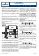
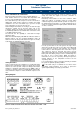
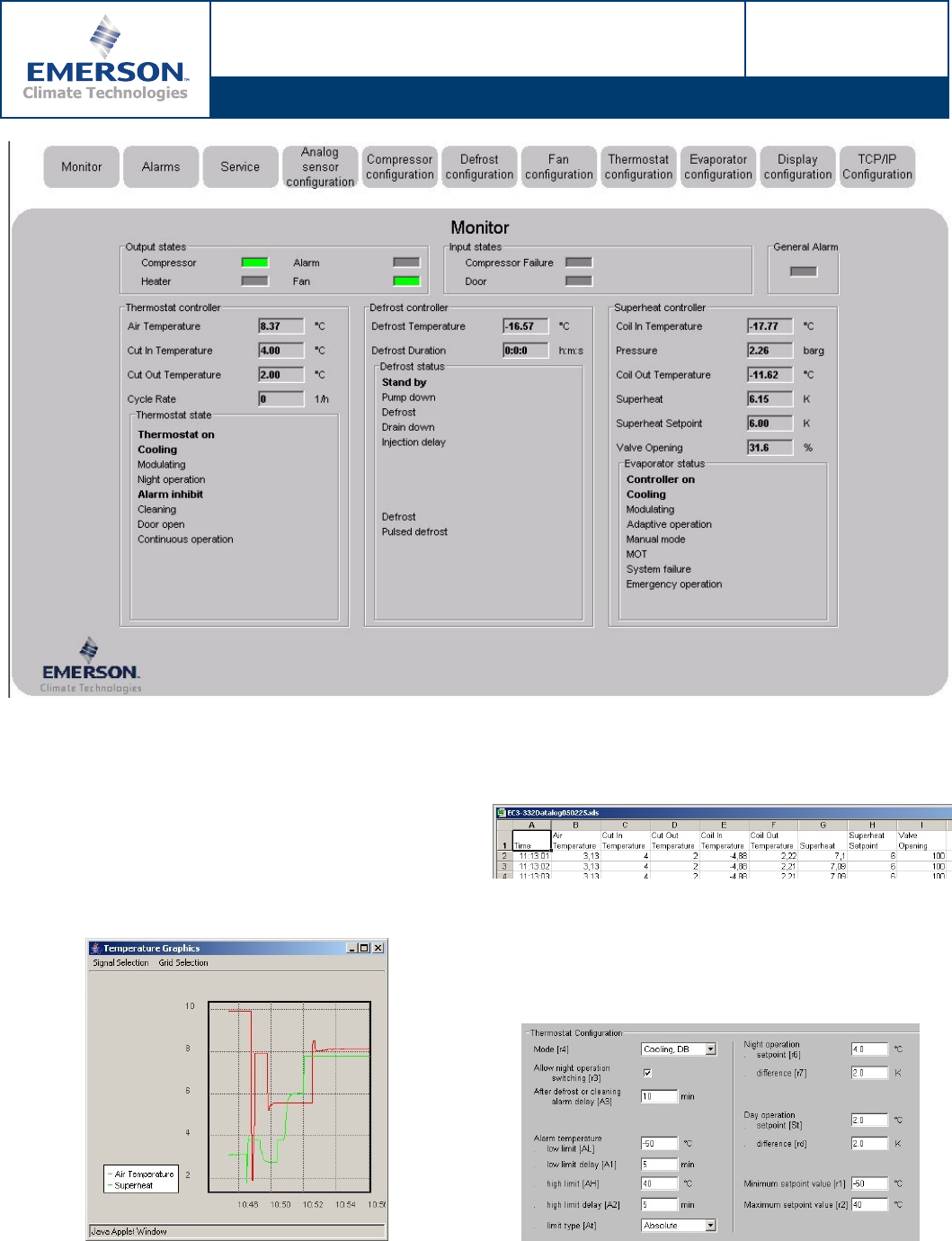
The top fields indicate the status of compressor, defrost heater,
fan and alarm output relay (left) and the status of compressor
alarm loop and door switch inputs (right). The fields below show
temperatures and pressure of all sensors attached to the
controller as well as the setpoints for air temperature and
superheat. The coil-in temperature is calculated from the
saturation pressure of the used refrigerant. All status messages
(thermostat, defrost and evaporator) are displayed in the lower
section with normal font, all active messages are in bold letters.
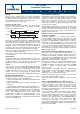
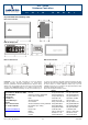
A rolling graph with air temperature and superheat data over a
period of approximately 10 minutes can be displayed:
A logfile can be stored on the PC. The file format of the datalog
is text with semicolon (;) separated fields. On the picture below
is a sample log file from an EC3-332 imported in Microsoft
Excel
®
:
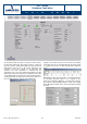
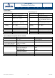
All WebPages, which allow the change of controller parameters
are password protected. Below is the example for the
thermostat configuration WebPage of an EC3-332 Controller.
The setpoints of day and night operation, as well as the settings
which will initiate an alarm can be easily reviewed and modified
if needed: