
Installation manual


Serial Communication Parameters
138 S1A53838 09/2011
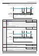
Network communication between the ATV212 drive and a master controller
(1) For additional information, refer to NEMA ICS 1.1 (latest edition), “Safety Guidelines for the Application, Installation, and Maintenance of Solid
State Control” and to NEMA ICS 7.1 (latest edition), “Safety Standards for Construction and Guide for Selection, Installation and Operation
of Adjustable-Speed Drive Systems.”
Network communication between the ATV212 drive and a master controller is possible through five protocols
selectable through the embedded display terminal:
z Modbus
®
RTU
z Metasys
®
N2
z Apogee
®
P1 FLN
z BACnet
z LonWorks
®
Three types of data exchange are possible:
z Monitoring: monitoring values such as output frequency, voltage, and current
z Programming: reading, editing, and writing drive parameters
z Control: starting and stopping the drive and controlling the frequency reference
For operation on a network containing multiple drives, each ATV212 drive needs to be assigned a unique
address using parameter F802.
For operation on a network where all drives are slaves responding to a central control system:
z Parameters [Command mode sel] (CNOd) (see page 77) and [Frequency mode sel] (FMOd) (see page
77
) needs to be set correctly:
- Setting CMOd to 2 enables start/stop control of the drive via network communication
- Setting FMOd to 4 enables the frequency reference to be controlled by network communication
- Setting either CMOd to 2 or FMOd to 4 enables serial communication error detection. The setting of
parameter F851 determines the drive’s response in case of a loss of communication.
Control of the ATV212 drive can be established by a master controller over a serial communication network
regardless of the setting of CMOd or FMOd (see diagram on page 46
). Control can be restored to the source
defined by CMOd and FMOd if the serial communication network relinquishes control or a logic input
assigned to function 48 (forced local) is enabled.
WARNING
LOSS OF CONTROL
• The designer of any control scheme must consider the potential failure modes of control paths and, for
certain critical control functions, provide a means to achieve a safe state during and after a path failure.
Examples of critical control functions are emergency stop and overtravel stop.
• Separate or redundant control paths must be provided for critical control functions.
• System control paths may include communication links. Consideration must be given to the implications of
unanticipated transmission delays or failures of the link (1).
Failure to follow these instructions can result in death, serious injury, or equipment damage.
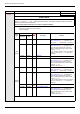
Code Name / Description Adjustment
range
Factory
setting
F800 [Mdb RJ45 baud]
Modbus RJ45 baud rate - 1
0
1
[9600 bps]
[19200 bps]
F801 [Mdb RJ45 parity]
Modbus RJ45 parity - 1
0
1
2
[No]: No parity
[Even]: Even parity
[Odd]: Odd parity
F802 [Modbus address]
0 to 247 1
This address is used whatever the port used.