
Installation manual


I/O Control Parameters
S1A53838 09/2011 111
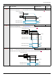
F366 [PID Derivative Gain]
0.00 to 2.55 0.00
Parameter F366 adjusts the derivative gain applied during PID control. This gain adjusts the response time of the drive to rapid
changes in the process.
Increasing the setting of F366 more than necessary may cause great fluctuations in motor speed resulting in system instability.
The diagram below illustrates the effect produced by adjusting F366.
F359 [PID ctrl wait time]
PID Control Waiting Time 0 to 2400 s 0
If parameter F359 is set to a value greater than 0 seconds, the drive will not immediately enter PID control upon startup. For
the time set by F359, the drive will ignore the feedback signal, accelerating the motor to the speed set by the reference input.
This function can be used to help prevent the drive from entering PID control mode before the system approaches the final op-
erating level.
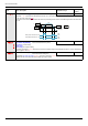
F380 [PID reverse error]
PI regulator reversal direction correction 0
0
1
[No]
[Yes]
This function is used to reverse the error PI for Water Pump.
If F380 = 0 or No, PI error input = reference - feedback. The motor speed increases when the error is positive.
If F380 = 1 or Yes, PI error input = feedback - reference. The motor speed decreases when the error is positive.
F391 [Stop on LL hyst]
Stop on LL hysteresis
0.0 to [Max frequency]
(FH)
0.2 Hz
F392 [PID wake up (thres)]
PI wake up threshold on PI error 0.0 to [Max frequency]
(FH)
0.0 Hz
DANGER
UNINTENDED EQUIPMENT OPERATION
Check that unintended restarts will not endanger personnel or equipment in any way.
Failure to follow these instructions will result in death or serious injury.
F393 [PID wake up, feedb]
PI wake up threshold on PI feedback error 0.0 to [Max frequency]
(FH)
0.0 Hz
DANGER
UNINTENDED EQUIPMENT OPERATION
Check that unintended restarts will not endanger personnel or equipment in any way.
Failure to follow these instructions will result in death or serious injury.
F645 [Mot PTC selection]
PTC Motor Thermal Protection Enable - 0
0
1
2
[Disabled]
[Enabled fault] (detected fault mode). If F645 is set to 1 and the PTC probe exceeds a given, threshold, the drive will trip and
display an [PTC overheating] (OH2) code.
[Enabled alarm] (alarm mode). If F645 is set to 2 and the PTC probe exceeds a given, threshold, the drive will signal a de-
tected fault and continue operating.
Setting parameter F645 to 1 or 2 converts control terminal VIB into a PTC motor thermal probe input. See the ATV212 Instal-
lation manual, for wiring details.
Code Name / Description Adjustment range
Factory set-
ting
Current Error
Previous
Error
Feedback
Amount
Small Derivative Gain
Large Derivative Gain
Motor Speed Change
Time