
Installation manual


I/O Control Parameters
S1A53838 09/2011 109
Code Name / Description Adjustment range
Factory set-
ting
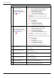
F691 [AO slope]
Analog Output Slope - 1
0
1
[Negative slope]
[Positive slope]
F692 [Analog output bias]
0 to 100% 0%
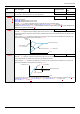
Refer to the diagram below for examples of adjusting parameters [AO scaling] (FM), [AO slope] (F691), and F692.
F694 [Freq. for AO = 0V]
Low frequency when analog output equal 0 V 0 Hz to [Max frequency]
(FH) Hz
0 Hz
Refer to the diagram below for adjusting parameters F694, and [Freq. for AO = 10V] (F695).
F695 [Freq. for AO = 10V]
High frequency when analog output equal 10 V 0 Hz to [Max frequency]
(FH) Hz
0 Hz
Refer to the diagram above for adjusting parameters [Freq. for AO = 0V] (F694), and F695.
F130 [RY Relay Function 1]
RYA-RYC Relay Function 0 to 69, 254, 255 4
For a complete description of the various functions assignable to the RYA-RYC relay, see page 98.
The RYA-RYC relay can have a secondary assignment with programmed selection logic. See parameters
[RY Relay Function 2] (F137) and [RY logic select.]
(F139) on page 113 for more detail.
F146 [RY delay]
Delay for RYA-RYC Relay
0.0 to 60.0 s 0.0 s
This parameter introduce a delay on RYA-RYC output signal relay.
F132 [FL Relay Function]
Function for FL Relay 0 to 69, 254, 255
11
For a complete description of the various functions assignable to the FL relay, see page 98.
=
,
=
(mA)
20
0
0
100%
=
,
=
(mA)
20
4
0
100%
=
,
=
(mA)
20
0
0
100%
=
,
=
(mA)
20
4
0
100%
FMSL signal value
Output Current
:Large Gain
:Small Gain
Output Current
Output
Current
FMSL signal value
FMSL signal valueFMSL signal value
Output
Current
10 V
0 V
F694
F695
10 V
0 V
F695
F694
Speed reference
Motor frequency
Internal reference (after PID)
Speed reference
Motor frequency
Internal reference (after PID)