
Installation manual


I/O Control Parameters
106 S1A53838 09/2011
Analog Input Adjustments
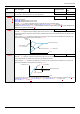
Analog Input Speed Reference and Output Frequency
Do not set the same frequency values for both output frequency levels 1 and 2. This will cause an Err1
detected fault.
When using a 4–20 mA signal, set speed reference level 1 value to 20% (4 ÷ 20 = 20%).
A further refinement of the bias and slope of the analog input signals can be made with parameters F470 –
F473.
Output Frequency Hz
20 mA
or
10 V
Speed Reference %
F203F201
F202
F204
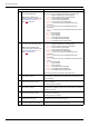
Code Name / Description Adjustment range Factory setting
F201 [VIA ref point 1]
VIA speed reference level 1 0 to 100% 0%
F202 [VIA freq. point 1]
VIA output frequency level 1 0.0 to 200.0 Hz 0.0 Hz
F203 [VIA ref point 2]
VIA speed reference level 2 0 to 100% 100%
F204 [VIA freq. point 2]
VIA output frequency level 2 0.0 to 200.0 Hz 50.0 Hz
F160 [VIA rel thresh. logic]
Threshold logic for relay link to VIA 0 to 100% 0%
F161 [VIA threshold hyst.]
Hysteresis threshold for logic relay link to VIA 0 to 20% 3%
F210 [VIB ref. point 1]
VIB speed reference level 1 0 to 100% 0%
F211 [VIB freq. point 1]
VIB output frequency level 1 0.0 to 200.0 Hz 0.0 Hz
F212 [VIB ref. point 2]
VIB speed reference level 2 0 to 100% 100%
F213 [VIB freq. point 2]
VIB output frequency level 2 0.0 to 200.0 Hz 50.0 Hz
F162 [VIB rel thresh. logic]
Threshold logic for relay link to VIB 0 to 100% 0%
F163 [VIB threshold hyst.]
Hysteresis threshold for logic relay link to VIB 0 to 20% 3%