
Technical data


Settings MIQ/CR3; DIQ/CR3
4 - 22
ba76032e01 01/2012
4.5.6 Pulse-width contr.
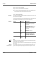
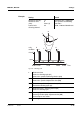
Function The characteristic of the pulse width output is laid down in the Start
value, End value, Pulse width (v) min. and Pulse width (v) max.
settings. The fundamentals of the function are described in the
introductory chapter (see section 4.1.3).
In order to set up the Pulse-width contr. function for a relay output, the
relay output must be linked with a sensor (see section 4.3).
Settings
Characteristic curve You can specify the minimum and maximum pulse width (v). This
determines the steepness of the characteristic curve of the output.
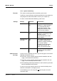
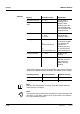
Setting Selection/Values Explanation
Measured variable Main variable
Adjoining variable
Main variable
designates the
actual measured
parameter of the
sensor (e.g. pH,
oxygen, etc.).
Adjoining variable
designates an
additional measured
parameter (e.g.
temperature).
Start value within the
measuring range
(sensor-
dependent)
Minimum spacing:
5 % of the
measuring range
End value
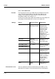
Pulse width (v) min. 0 ... 100 % Minimum spacing:
10 % of the Cycle
duration (T)
Pulse width (v) max.
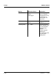
Cycle duration (T) 5 ... 100 s Length of the
switching period T
T = (t
on
+ t
off
)
Error pulse width 0 ... 100 % In case of system
errors or sensor
errors (see page 4-
39), the relay
switches with the
pulse-width
specified.
Action Open
Close
Relay action (see
section 4.5.1)