
Technical data


MIQ/CR3; DIQ/CR3 Installation
3 - 5
ba76032e01 01/2012
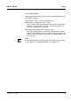
Connecting lines to the
terminal strip
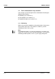
Fig. 3-1 Terminal strip with the relay and current connections
Warning
No free wires must be allowed to project into the enclosure.
Otherwise, there is a danger that safe areas could come into
contact with dangerous voltages. This could result in life
threatening electric shock when working with the IQ S
ENSOR NET.
Always cut off any wires that are not in use as closely as possible
to the cable gland.
1 Open the module.
2 Screw the cable gland (pos. 1 in Fig. 3-1) with the sealing ring
(pos. 2) into the module housing.
3 Loosen the coupling ring (pos. 3 in Fig. 3-1).
4 Feed the line through the cable gland in the module housing.
5 Connect the wires to the terminal strip. While doing so, pay
attention to the specifications on the label located under the
terminal strip.
6 Tighten the coupling ring (pos. 3 in Fig. 3-1).
1
3
2
Relay Current output
X18 X17
250 VAC
5AAC
R1
X16 X15
250 VAC
5AAC
R2
X14 X13
250 VAC
5AAC
R3
X12 X10 X8X11 X9 X7
0/4...20mA 0/4...20mA 0/4...20mA
+ REC -
C1
+ REC -
C2
+ REC -
C3
X6 X5 X4
SENSORNET 2
RED
SHIELD
GREEN
X3 X2 X1
SENSORNET 1
RED
SHIELD
GREEN
ON
OFF
SN TERMINATOR