Operating manual IQ SENSOR NET MIQ/CR3; DIQ/CR3 OK er Pow ! IQ SENSOR NET combi output module ba76032e01 01/2012
MIQ/CR3; DIQ/CR3 Note For the most recent version of the manual, please visit www.ysi.com. Contact Copyright 2 YSI 1725 Brannum Lane Yellow Springs, OH 45387 USA Tel: +1 937-767-7241 800-765-4974 Email: environmental@ysi.com Internet: www.ysi.com © 2012 Xylem Inc.
MIQ/CR3; DIQ/CR3 List of contents MIQ/CR3; DIQ/CR3 - List of contents 1 Overview . . . . . . . . . . . . . . . . . . . . . . . . . . . . . . . . . . . . 1-1 1.1 1.2 2 Safety instructions . . . . . . . . . . . . . . . . . . . . . . . . . . . . 2-1 2.1 2.2 3 3.3 3.4 4.2 4.3 4.4 4.5 4.6 01/2012 Scope of delivery . . . . . . . . . . . . . . . . . . . . . . . . . . . . . . 3-1 Installation in the IQ SENSOR NET . . . . . . . . . . . . . . . . . 3-1 3.2.
List of contents MIQ/CR3; DIQ/CR3 4.7 4.8 4.9 5 Maintenance and cleaning . . . . . . . . . . . . . . . . . . . . . 5-1 5.1 5.2 Maintenance . . . . . . . . . . . . . . . . . . . . . . . . . . . . . . . . . .5-1 Cleaning . . . . . . . . . . . . . . . . . . . . . . . . . . . . . . . . . . . . .5-1 6 Technical data . . . . . . . . . . . . . . . . . . . . . . . . . . . . . . . 6-1 7 Contact Information . . . . . . . . . . . . . . . . . . . . . . . . . . . 7-1 7.1 7.2 8 Ordering & Technical Support .
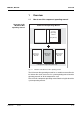
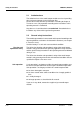
MIQ/CR3; DIQ/CR3 Overview 1 Overview 1.1 How to use this component operating manual Structure of the IQ SENSOR NET operating manual IQ Sensor Net Operating Manual System Operating Manual (Ring Binder) IQ Sensor Operating Manual MIQ Module Operating Manual MIQ Terminal Operating Manual Component Operating Manuals Fig. 1-1 Structure of the IQ SENSOR NET operating manual The IQ SENSOR NET operating manual has a modular structure like the IQ SENSOR NET itself.
Overview MIQ/CR3; DIQ/CR3 1.2 General characteristics Features of the combi output module The combi output module has three current outputs and three relay outputs. You can link current outputs and relay outputs to sensors. The linked current outputs and relay outputs can, for example, be used to monitor sensors or to output measurement data. Unlinked relay outputs can be used for general monitoring functions.
MIQ/CR3; DIQ/CR3 Safety instructions 2 Safety instructions This operating manual contains special instructions that must be followed during the installation of the combi output module. Thus, it is essential for the operator to read this component operating manual before carrying out any work with the system. In addition to this manual, the SAFETY chapter of the IQ SENSOR NET system operating manual must be followed.
Safety instructions MIQ/CR3; DIQ/CR3 2.1 Authorized use The authorized use of the combi output module consists of providing relay and current outputs in the IQ SENSOR NET. Please observe the technical specifications according to chapter 6 TECHNICAL DATA. Only operation according to the instructions in this operating manual is authorized. Any other use is considered to be unauthorized. Unauthorized use invalidates any claims with regard to the guarantee. 2.
MIQ/CR3; DIQ/CR3 Installation 3 Installation 3.1 Scope of delivery The scope of delivery of the combi output module is listed in the INSTALLATION chapter of the system operating manual. 3.2 Installation in the IQ SENSOR NET The IQ SENSOR NET provides a number of options for integrating the combi output module mechanically and electrically in the system (stacked mounting, distributed mounting, etc.).
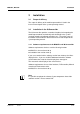
Installation MIQ/CR3; DIQ/CR3 3.3 Cable glands Electrical connections: General instructions All electric cables are fed from below via prepared openings in the enclosure of the module. Cable glands with different clamping ranges are included with the module to provide sealing between the cable and enclosure as well as for strain relief. Select the matching cable gland for the respective cable diameter: Small, clamping range 4.5 to 10 mm.
MIQ/CR3; DIQ/CR3 General installation instructions Installation Observe the following points when attaching connecting wires to the terminal strip Shorten all wires to be used to the length required for the installation Always fit all the ends of the wires with wire end sleeves before connecting them to the terminal strip Any wires that are not used and project into the enclosure must be cut off as closely as possible to the cable gland.
Installation MIQ/CR3; DIQ/CR3 3.4 Connections to the relay and current outputs Warning If external electrical circuits that are subject to the danger of physical contact are incorrectly connected to the relay contacts, there may be a danger of life threatening electric shock. Electrical circuits are regarded to be subject to the danger of physical contact when there are voltages higher than the Safety Extra Low Voltage (SELV).
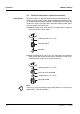
MIQ/CR3; DIQ/CR3 Connecting lines to the terminal strip Installation 1 Open the module. 2 X15 X13 R3 X10 X9 X8 X7 + REC C1 + REC C2 + REC C3 X6 X5 X4 ON OFF SENSORNET 2 X3 X2 X1 GREEN R2 X11 GREEN R1 X12 0/4...20mA 0/4...20mA 0/4...20mA RED 250 VAC 5 A AC Relay Fig. 3-1 X14 250 VAC 5 A AC RED X16 SHIELD X17 250 VAC 5 A AC SN TERMINATOR X18 SHIELD 1 3 SENSORNET 1 Current output Terminal strip with the relay and current connections 2 Screw the cable gland (pos.
Installation MIQ/CR3; DIQ/CR3 7 3-6 Close the module.
MIQ/CR3; DIQ/CR3 Settings 4 Settings The combi output module has three relays outputs and three current outputs. Relay outputs operate as openers or closers. Current outputs provide a current that depends on the measured value. On the terminal or Universal Transmitter, you can assign names to the outputs (with the 2020 XT system only, see section 4.2). link outputs with sensors (see section 4.3) delete links of outputs with sensors (see section 4.4) adjust outputs (see section 4.
Settings MIQ/CR3; DIQ/CR3 4.1 Basic information on relay functions In this chapter, you will find general basic information concerning the following relay functions: Monitoring (see section 4.1.1) Limit indicator (see section 4.1.2) Proportional output (see section 4.1.3) 4.1.1 Monitoring When using a relay for monitoring, a relay action (Open, Close) occurs when certain states occur. This function is suitable, e.g. for the monitoring of errors in the system.
MIQ/CR3; DIQ/CR3 Settings 4.1.2 Limit indicator With a limit indicator, a relay switches when a specified limiting value is exceeded or undercut. Limit indicators can be used in the following way: Monitoring a limiting value using a relay: when a limiting value (upper or lower limiting value) is exceeded or undercut, a relay switches. The Open or Close relay actions are possible in each case (see page 4-4).
Settings Monitoring limiting values using one or two relays MIQ/CR3; DIQ/CR3 Measured value t1 t1 Relay 1 UL Hysteresis UL 2 1 6 4 3 5 LL Hysteresis LL Relay 2 t2 t2 Time Fig.
MIQ/CR3; DIQ/CR3 Settings 4.1.3 Proportional output In the case of proportional output, a relay switches cyclically on and off in a defined measured value range (proportional range). At the same time, the relay switches with a: duration of operation that corresponds to the measured value (pulse-width output, see page 4-7) or switching frequency (frequency output, see page 4-8).
Settings Output with one relay MIQ/CR3; DIQ/CR3 Switching frequency f or Pulse width v 100 90 Proportional band 10 0 Measured value 1 Fig. 4-2 Output with two relays 2 Output with one relay Switching frequency f or Pulse width v Proportional bands Relay 1 and 2 100 90 10 Measured value 0 1 2 Relay 1 Fig.
MIQ/CR3; DIQ/CR3 Pulse width output Settings The output of the pulse width is used, e.g. for controlling valves. Pulse-width regulation changes the duration of operation (ton) of the output signal. Depending on the position of the measured value in the proportional range, the relay is operated for a longer or shorter time period. Relay tOn t Off On Off T Fig.
Settings Frequency output MIQ/CR3; DIQ/CR3 Switching frequency output is used, e.g. for controlling dosing pumps. In contrast to the pulse-width output, not the pulse width is modulated with frequency output but the switching frequency of the output signal. Depending on the position of the measured value in the proportional range, the relay is switched more often or less often. Relay tOn = 0.3 s On Off T Fig.
MIQ/CR3; DIQ/CR3 Characteristic curves Settings Through the selection of the Start value and End value, the proportional output can be operated with a positive or negative characteristic curve. Positive characteristic curve: Select the End value to be greater than the Start value. The turn-on duration or frequency increases with an increasing measured value (see page 4-10). Negative characteristic curve: Select the End value to be smaller than the Start value.
Settings Positive characteristic curve MIQ/CR3; DIQ/CR3 The proportional output range begins above the initial value. If the proportional range is undercut or exceeded, the selected behavior comes into force. Pulse width v [%] 90% 100 90 Cycle duration T 50 Proportional band 10 0 50% 50% tOn tOf f 10% 90% Time 1 Fig.
MIQ/CR3; DIQ/CR3 Negative characteristic curve Settings The proportional output range begins below the initial value. If the proportional range is undercut or exceeded, the selected behavior comes into force. Pulse width v [%] 90% 100 90 10% Cycle duration T 50 Proportional band 10 0 50% 50% tOn tOf f 10% 90% Time 2 Measured value 1 Fig.
Settings MIQ/CR3; DIQ/CR3 4.2 Entering / editing the name of an output For easier identification of the outputs, an individual name can be given to each output in the Edit list of outputs overview. This option is available with the 2020 XT system only. 1 Open the Settings menu with s. 2 Using d and g, select and confirm the menu item, System settings -> Edit list of outputs. The Edit list of outputs display opens. 3 Highlight a name in the Name column with d and confirm with g. Fig.
MIQ/CR3; DIQ/CR3 Settings 4.3 Linking the output with a sensor The following steps describe operation with the 2020 XT system. With the System 182 XT, the outputs of the DIQ/CR3 can be found directly under the Settings menu (see system operating manual of the DIQ/ S 182 XT). 1 Open the Settings menu with s. 2 Using d and g, select and confirm the menu item, System settings -> Settings of outputs and links. The Settings of outputs and links display opens.
Settings MIQ/CR3; DIQ/CR3 4.4 Deleting a link with an output If a link from a current or relay output with a sensor is no longer required, the link can be deleted. The following steps describe operation with the 2020 XT system. With the System 182 XT, the outputs of the DIQ/CR3 can be found directly under the Settings menu (see system operating manual of the DIQ/ S 182 XT). 1 Open the Settings menu with s.
MIQ/CR3; DIQ/CR3 Settings 4.5 Setting the relay outputs The following steps describe operation with the 2020 XT system. With the System 182 XT, the outputs of the DIQ/CR3 can be found directly under the Settings menu (see system operating manual of the DIQ/ S 182 XT). 1 Call up the measured value display with m. 2 Open the Settings menu with s. 3 Highlight the Settings of outputs and links menu item with d and confirm with g. The Settings of outputs and links display appears.
Settings MIQ/CR3; DIQ/CR3 Function Description No function The relay output is not used. System monitoring see section 4.5.2 Sensor monitoring see section 4.5.3 Limit indicator see section 4.5.4 Frequency controller see section 4.5.5 Pulse-width contr. see section 4.5.6 Cleaning see section 4.5.7 Sensor-controlled see section 4.5.8 Manual control see section 4.5.9 Alarm contact see section 4.5.10 8 Carry out the settings for the relay outputs with d and g.
MIQ/CR3; DIQ/CR3 Settings 4.5.2 Function System monitoring The System monitoring enables to monitor system errors. In order to set up the System monitoring function for a relay output, the relay output must not be linked with a sensor (see section 4.3). It can be used to monitor the following system errors.
Settings MIQ/CR3; DIQ/CR3 The sensor is being calibrated The sensor is in the maintenance condition The sensor is being cleaned with the aid of a valve module in the system (compressed air operated cleaning system). 4.5.3 Function Sensor monitoring The Sensor monitoring function enables to monitor sensor errors and the maintenance condition. In order to set up the Sensor monitoring function for a relay output, the relay output must be linked with a sensor (see section 4.3).
MIQ/CR3; DIQ/CR3 General sensor errors Settings Init can prompt a relay action for a short time, depending on the starting behavior of the system ---- Invalid measured value, or defective sensor Error Communication with sensor interrupted OFL Measuring range undercut or exceeded (overflow) 4.5.4 Function Limit indicator The characteristic of the limit indicator is laid down in the Limit value UL, Limit value LL, Hysteresis UL and Hysteresis LL settings.
Settings 4 - 20 MIQ/CR3; DIQ/CR3 Setting Selection/Values Explanation Behavior at error Open Close Unchanged The relay opens, closes, or remains unchanged in case of system errors or sensor errors (see page 4-39). Action Open Close Relay action (see section 4.5.1) Switching delay 0 ... 3600 s The time period for which a limiting value must be exceeded before the relay operates. Prevents frequent switching for measured values that are close to the limiting value.
MIQ/CR3; DIQ/CR3 Settings 4.5.5 Function Frequency controller The characteristic of the frequency output is laid down in the Start value, End value, Frequency (f) min. and Frequency (f) max. settings. The fundamentals of the function are described in the introductory chapter (see section 4.1.3). In order to set up the Frequency controller function for a relay output, the relay output must be linked with a sensor (see section 4.3).
Settings MIQ/CR3; DIQ/CR3 4.5.6 Function Pulse-width contr. The characteristic of the pulse width output is laid down in the Start value, End value, Pulse width (v) min. and Pulse width (v) max. settings. The fundamentals of the function are described in the introductory chapter (see section 4.1.3). In order to set up the Pulse-width contr. function for a relay output, the relay output must be linked with a sensor (see section 4.3).
MIQ/CR3; DIQ/CR3 Settings 4.5.7 Cleaning Note When using the MIQ/CHV PLUS valve module, it is best to set the Cleaning function directly at the valve output (V) of the MIQ/CHV PLUS (see operating manual of the MIQ/CHV PLUS). The relay can then be used for other purposes. Function The Cleaning function enables the time controlled automatic start of the sensor cleaning function with the aid of a relay of the combi output module.
Settings MIQ/CR3; DIQ/CR3 Settings Setting Selection/Values Explanation Reference time (h) 0 ... 23 h Reference time (min) 0 ... 60 min Time at which a cleaning cycle is started. Further cleaning cycles will be performed at the times specified by the cleaning interval. Interval unit 1 .. 7 d 1 .. 24 h 5 .. 60 min Selection of range and unit for the Cleaning interval.
MIQ/CR3; DIQ/CR3 Example Settings Setting Result Reference time (h): Reference time (min): Interval unit: Cleaning interval: 12 0 Hours (h) 8h Reference time: 12:00 hours This specifies the following start times: 04:00, 12:00 and 20:00 hours 2 1 3 t1a t1b relay condition 4 t1 1 4 t1 t1 closed open t2 t2 00:00 04:00 t2 12:00 t2 20:00 24:00 Time Fig.
Settings Canceling the cleaning MIQ/CR3; DIQ/CR3 A running cleaning cycle is canceled: Automatically – If the sensor switches to the inactive condition during the cleaning cycle Manually – By pressing c – By switching on the maintenance condition Each time the cleaning cycle is canceled, the relay opens immediately. If the cleaning cycle is canceled automatically, the outputs linked to the sensor are released immediately.
MIQ/CR3; DIQ/CR3 Settings 4.5.8 Sensor-controlled With the Sensor-controlled function, the relay is controlled by a linked sensor. Requirements For the 2020 XT system, a controller with a software version from 2.80 up is required Sensor that transmits signals to trigger a cleaning cycle, e.g. UV/VIS sensor Settings Setting Selection/Values Explanation Pulse length Automatic The duration of the air cleaning process is programmed in the sensor.
Settings MIQ/CR3; DIQ/CR3 4.5.9 Function Manual control With the Manual control function, you can test the operativeness of an instrument that is connected to the relay. To do so, close or open the relay manually and, while doing so, check the behavior of the connected instrument. Setting Selection/Values Explanation Relay function Manual control The selected relay action is carried out with Save and quit. Action Open Close Relay action (see section 4.5.
MIQ/CR3; DIQ/CR3 Settings 4.6 Setting of current outputs The following steps describe operation with the 2020 XT system. With the System 182 XT, the outputs of the DIQ/CR3 can be found directly under the Settings menu (see system operating manual of the DIQ/ S 182 XT). 1 Call up the measured value display with m. 2 Open the Settings menu with s. 3 Highlight the Settings of outputs and links menu item with d and confirm with g. The Settings of outputs and links display appears.
Settings MIQ/CR3; DIQ/CR3 Function Settings No function The current output is not used. Recorder see section 4.6.1 PID controller see section 4.6.2 Fixed current value see section 4.6.3 8 Carry out the settings for the current output with d and g. 9 Highlight and confirm Save and quit with d and g. The new settings are stored. 4.6.1 Recorder Function The measured values of the linked sensor at the current output are set up as current intensity in the Recorder application.
MIQ/CR3; DIQ/CR3 Settings I -> OFL/UFL Behavior at error ba76032e01 01/2012 Error Current values outside the range between Start value and End value are considerd as errors. The current output reacts as specified under Behavior at error (see below). Limitation The current at the output is limited to the Start value or End value.
Settings MIQ/CR3; DIQ/CR3 4.6.2 Function PID controller With the PID controller function, you can use an output as a controller output. The controller can be configured as a Proportional controller with a switchable Integral and Derivative controller part (PID controller).
MIQ/CR3; DIQ/CR3 Settings By activating or deactivating the Integral (ti) and Derivative (td) controller part, the following controller types can be configured: Characteristic curve of the proportional controller Controller type td [s] ti [s] P controller 0 0 PI controller 0 1 to 9999 PD controller 1 to 9999 0 PID controller 1 to 9999 1 to 9999 For a P controller, the interrelationship between the measured value and current I at the controller output forms the following characteristic cur
Settings Application example MIQ/CR3; DIQ/CR3 Feedback control of the D. O. concentration Sensor: TriOxmatic 700 IQ (measuring range: 0 ...
MIQ/CR3; DIQ/CR3 Settings Within the proportional band, a concentration increase by 1 mg/l causes a decrease of the current output by 1 mA.
Settings 4 - 36 MIQ/CR3; DIQ/CR3 Setting Selection/Values Explanation Io 0 ... 20 mA Current value on the output if the measured value equals the Nominal value ti 0 ... 9999 s Hold-back time: Integral part of the controller (0 = not effective) td 0 ...
MIQ/CR3; DIQ/CR3 Settings 4.6.3 Function Fixed current value With the Fixed current value function, you can test the operativeness of the instruments connected to the outputs: output different current values to the output and, while doing so, check the behavior of the connected instrument. Setting Selection/Values Explanation Current output Fixed current value Using Save and quit, the nominal amperage that was input as Inom is output. Inom 0 ... 20 mA The nominal amperage that is output.
Settings MIQ/CR3; DIQ/CR3 4.7 Checking the status of the outputs This function offers a simple overview of the states of all outputs of the combi output module. For relays, the status open or closed is displayed. For current outputs, the current value available at the output is displayed. With the System 182 XT, you can recall the states of the outputs via the measured value and status display (see system operating manual of the DIQ/S 182 XT).
MIQ/CR3; DIQ/CR3 Settings 4.8 Behavior of linked outputs 4.8.1 Behavior in case of error For linked relay outputs or current outputs, you can determine the behavior of the outputs in case of errors. Depending on the use of the output, the behavior in case of errors is set in the following menus: Error events Output menu Frequency controller Frequency with error (see section 4.5.5) Pulse-width contr. Error pulse width (see section 4.5.6) Recorder Current with error (see section 4.6.
Settings MIQ/CR3; DIQ/CR3 4.8.2 Behavior in non-operative condition An output is non-operative when no function is activated for the output. An output becomes non-operative in case of Power failure (As soon as the supply voltage is sufficient again, the non-operative condition of the outputs ends. The outputs function as specified by the user again.
MIQ/CR3; DIQ/CR3 Settings 4.9 Maintenance condition of sensors The maintenance condition of sensors serves to calibrate, clean, service and repair (remove and replace) sensors. In the maintenance condition the system does not react to the current measured value or the condition of the selected sensor linked outputs are frozen sensor errors do not prompt changes in the conditions of linked outputs. The maintenance condition is automatically activated during calibration.
Settings MIQ/CR3; DIQ/CR3 4.9.1 1 Call up the measured value display with m. 2 Select the sensor you want to switch on the maintenance condition for with d. The measured values of the sensor do not flash. 3 Open the 300 - Display/Options menu with g. 4 Using d, highlight the menu item, Switch maintenance condition on/off or Maintenance of sensor S0x and confirm with g. A window that informs you about the maintenance condition opens up. 5 Confirm Continue with g.
MIQ/CR3; DIQ/CR3 Maintenance and cleaning 5 Maintenance and cleaning 5.1 Maintenance The combi output module does not require any special maintenance work. The general maintenance of IQ SENSOR NET components is described in the IQ SENSOR NET system operating manual. 5.2 Cleaning The cleaning of IQ SENSOR NET components is described in the IQ SENSOR NET system operating manual.
Maintenance and cleaning 5-2 MIQ/CR3; DIQ/CR3 ba76032e01 01/2012
MIQ/CR3; DIQ/CR3 Technical data 6 Technical data Note General technical data on MIQ modules are given in the TECHNICAL DATA chapter of the IQ SENSOR NET system operating manual. Electrical data Instrument safety Nominal voltage Max. 24 VDC via the IQ SENSOR NET (for details, see the TECHNICAL DATA chapter of the IQ SENSOR NET system operating manual) Power consumption 3W Protective class II Overvoltage category II Applicable norms – EN 61010-1 – UL 3111-1 – CAN/CSA C22.2 No. 1010.
Technical data MIQ/CR3; DIQ/CR3 Relays Output Physically separated from the IQ SENSOR NET Max. switching voltage 250 VAC or 24 VDC Max. switching current 5 A (AC and DC) Installation requirements Fuse rating on the operator side: Maximum 5A Relay functions – System monitoring – Sensor monitoring – Limit indicator – Frequency controller – Pulse-width contr.
MIQ/CR3; DIQ/CR3 Contact Information 7 Contact Information 7.1 Ordering & Technical Support Telephone: (800) 897-4151 (937) 767-7241 Monday through Friday, 8:00 AM to 5:00 PM ET Fax: (937) 767-1058 Email: environmental@ysi.com Mail: YSI Incorporated 1725 Brannum Lane Yellow Springs, OH 45387 USA Internet: www.ysi.com When placing an order please have the following information available: YSI account number (if available) Model number or brief description Quantity 7.
Contact Information 7-2 MIQ/CR3; DIQ/CR3 ba76032e01 01/2012
MIQ/CR3; DIQ/CR3 Indexes 8 Indexes 8.1 Explanation of the messages In this chapter you will find a list with all the message codes and corresponding message texts that may occur in the log book of the IQ SENSOR NET system for the MIQ/CR3 output module. Note Information about Contents and structure of the log book and Structure of the message code can be found in the LOG BOOK chapter of the IQ SENSOR NET system operating manual.
Indexes 8-2 MIQ/CR3; DIQ/CR3 ba76032e01 01/2012
1725 Brannum Lane Yellow Springs, Ohio 45387 USA +1 937-767-7241 800-765-4974 (US) FAX (937) 767-1058 Email: environmental@ysi.com Internet: www.ysi.