User Manual This version of the manual supports firmware 3308 and all handle trigger optimization.
Statement of Agency Compliance The CR3 has been tested for compliance with FCC regulations and was found to be compliant with all applicable FCC Rules and Regulations. IMPORTANT NOTE: To comply with FCC RF exposure compliance requirements, this device must not be co-located or operate in conjunction with any other antenna or transmitter. CAUTION: Changes or modifications not expressly approved by the party responsible for compliance could void the user’s authority to operate the equipment.
Code Reader 3.0 User Manual Copyright © 2005 Code Corporation. All Rights Reserved. The software described in this manual may only be used in accordance with the terms of its license agreement. No part of this publication may be reproduced in any form or by any means without written permission from Code Corporation. This includes electronic or mechanical means such as photocopying or recording in information storage and retrieval systems. NO WARRANTY. This technical documentation is provided AS-IS.
Table of Contents Chapter 1 - Getting Started ............................................................................................................... 1 1.1 - Introduction ............................................................................................................................ 2 1.2 - Unpacking .............................................................................................................................. 3 1.3 - Powering On/Off .......................................
2.10 - Continuous Scan ................................................................................................................ 30 2.11 - Continuous Scan Settings ................................................................................................ 31 2.11.1 - Continuous Scan - Sleep Time Out .......................................................................... 31 2.11.2 - Continuous Scan - Trigger Delays ............................................................................
4.11 - Lockout Link Mode ............................................................................................................. 49 Chapter 5 - Advanced Decode Performance ................................................................................. 50 5.1 - Continuous Illumination ........................................................................................................ 51 5.2 - Set Targeting Zone Tolerances............................................................................
Chapter 1 - Getting Started Save Settings C002332_09_CR3 User Manual - 1
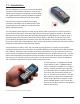
1.1 - Introduction The CR3 establishes a new benchmark for Portable Data Terminals and Hand Held Computers by combining the industry’s best imaging technology with a graphic display and rugged keyboard to create the smallest and lightest full-featured bar code reading terminal on the market. Using the same ergonomic platform as the highly successful Code Reader 2.0, the CR3 extends mobile all-symbology bar code reading to include information display and keyboard entry.
1.2 - Unpacking Remove the CR3 from its packing and inspect it for damage. If the scanner was damaged during shipping, please call Code at (801) 495-2200. The standard CR3 unit is shipped with a USB cable interface. The unit also features a 1950 mAH battery that must be installed in the unit at all times. Various accessories are available for the CR3. • 4 cable options (USB 6 ft., USB 12 ft.
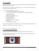
1.4 - Keypad/Icon Overview The chart below shows key/button functions.
The chart below shows all of the icons for CodeViewer™ software and their definitions. Icon Description Power Icons 50% to 100% capacity of battery 20% to 50% capacity of battery 0% to 20% capacity of battery – recharge battery as soon as possible Battery is recharging No icon is displayed when battery blank is used with a cabled reader Connection Icon Reader is connected physically or wirelessly to a receiving device (computer, handheld, etc.
1.5 - Batch Operation 1.5.1 - Introduction Batch data storage and data transfer are controlled by the resident JavaScript application on your CR3 reader. Please consult the Code Viewer user manual for the application on your CR3 for instructions on how to control data storage and transfer. 1.5.2 - RS232 Considerations In RS232 Batch Cable-Detect mode, the CR3 will detect if it is connected to a powered serial cable, and will send the data.
1.6 - Cabled Operation 1.6.1 - Introduction The CR3 is available with USB, RS232 and PS2 cables. All of the cables are connected to the CR3 with a 8-pin DIN connector. Different cables may be required for different hosts. Hand Held CR3 - To install a cable on the standard palm-held unit, correctly line up the 8-pin DIN connector into back end of the unit. The arrows on the connector should be facing down (Figure 1.2). When they are lined up, firmly push the cable in.
1.6 - Cabled Operation 1.6.2 - USB Cable Installation Guide To connect the CR3 to your host computer via USB interface: 1. Make sure the USB cable is sufficiently attached to your CR3 unit (Figure 1.7). 2. You DO NOT need to power off your host computer (Figure 1.8). The CR3 with USB interface can be plugged into any host while the computer is powered up. 3. Connect the USB interface cable to the host (Figure 1.9).
1.6.2.1 - USB Communication Settings USB Keyboard Mode - Data is sent from the Reader and interpreted by the host just as if a US keyboard was being used to enter data. USB Downloader - This mode is the standard way of transferring batch files or new firmware through the USB port. USB Native Two Way Mode - This mode is utilized when there is a need for error-corrected communication between the CR3 and an application through the USB port.
1.6.3 - PS2 Cable Installation Guide 1. Power off the host computer. 2. Attach the end of the PS2 cable with the single connector A to the CR3. 3. Disconnect your keyboard from the host and connect the appropriate connector to the PS2 cable B . 4. Connect the other connector to host computer into keyboard port C . Power on the host computer. The CR3 is powered by the PS2 port and does not require a power supply. A C B B C A Code does not guarantee compatibility with all models of laptops. 5.
1.6.4 - RS232 Cable Installation Guide To connect the CR3 to your host computer via RS232 interface: 1. Make sure the RS232 cable is sufficiently attached to your unit. 2. Connect the RS232 interface cable to your host computer (Figure 1.10). If you are unsure of the proper location to connect the RS232 cable please consult the manual of your host computer. 3. The RS232 interface can be purchased with a power supply. Plug the power supply adapter into the RS232 interface cable (Figure 1.
1.6.4.1 - RS232 Communication Data Bit Settings Scan the following codes to set the appropriate data bit: 7 Data Bits 8 Data Bits (Default) 1.6.4.2 - RS232 Communication Stop Bit Settings Scan the following code to set the appropriate stop bit data: 2 Stop Bits (Default) 1.6.4.3 - RS232 Communication Baud Rate Settings Scan the following codes to set the appropriate baud rate: 1200 2400 4800 9600 19200 38400 57600 (Default) 115200 1.6.4.
1.6.5 - Cabled Reader - Time Out Settings Scan one of the codes below to set the amount of time a cabled CR3 will be enumerated before entering sleep mode.
1.7 - Bluetooth Radio Operation 1.7.1 - Introduction This CR3 features a Bluetooth® wireless radio. The radio allows for point-to-point wireless communication with other Bluetooth devices that support serial port protocol (SPP). The following guide will give you general instructions on connecting your CR3 to a desktop or laptop computer with a Bluetooth radio.
Radio Range and Transferring Data The CR3 radio is a Class 1 device. If connected to another Class 1 device the unit has roughly a 300 foot line of sight operating range. If connecting to a Class 2 or Class 3 device, the operating range may drop to match the lower range. Once a unit is connected, the application software on the host must be open to receive data. When the CR3 detects the radio is out of range, the CR3 will store data on the reader’s non-volatile memory.
Save Settings Scan the code below to make the RF settings permanent on the reader: Save Settings Disconnecting from the Device You may force disconnection by reading the disconnect code below (The CR3 may not appear disconnected in the slave Bluetooth connection manager for 10 – 15 seconds after the command is issued). The CR3 will also disconnect after 90 seconds of inactivity (Note: You may change the radio sleep time out setting; however, it may reduce battery life).
1.7.3 - Bluetooth Radio Auto Disconnect Auto Disconnect: This feature is used when multiple CR3 units are connecting to the same Bluetooth Radio. By enabling Auto Disconnect the CR3 radio disconnects after each data transmission, allowing other radios to connect.
1.8 - Reader Feedback Guide The chart below shows potential icon combinations in CodeViewer™ software. Consult the chart to verify a configuration. Possible CR3 Configurations RS232 PS2 USB Bluetooth Radio RS232 One Way Mode PS2 Keyboard Mode USB One Way Mode Bluetooth One Way Mode This mode is the standard way of transferring unformatted, unpacketized data through the serial/RS232 port. This mode is the standard mode for transferring data from the CR3 through a PS2 port.
1.9 - Targeting and Reading Techniques The CR3 utilizes digital camera technology to take a picture of a symbol. Once an image is captured, the CR3 utilizes advanced decoding algorithms to extract data from the captured image. The CR3 is available as a palm-held unit or users may purchase a handle (available in various types). The palm held unit features left and right triggers. These triggers may be programmed to perform various features.
3. Hold the CR3 still - DO NOT SWIPE OR MOVE THE READER. Press the trigger until the CR3 beeps, indicating the code has been successfully decoded. 4. The reader may be optimized to your specific environment by scanning codes in Chapter 2. 1.10 - Imager Field of View and Resolution The CR3’s dual field optical system may be modified based on your scanning environment.
1.11 - Decode Zone Figure 1.
1.12 - Attaching Handles H1 - Handle 1. Place the CR3 in the cradle of the handle and slide the unit back (Figure 1.18). Be careful not to place fingerprints on the front glass when attaching handle. 2. Once the 8-pin DIN connector of the handle begins to enter the opening in the back of the unit, firmly press the unit back until the unit is flush against the handle (Figure 1.19). Figure 1.18 Figure 1.19 BH1 or BH2 Battery Handle 1. Make sure the reader has no battery or battery blank installed. 2.
1.13 - Reader Battery Installation Attaching and Detaching the Lithium Ion Battery The CR3 can be purchased with a 1950 mAH Lithium Ion battery. To install battery, make sure the battery is in the correct position (figure 1.21). Place the plastic tab of the battery into the reader (figure 1.22). Push the battery in and slide the locking mechanism down (figures 1.23 & 1.
Chapter 2 - Optimization and Trigger Programming Save Settings C002332_09_CR3 User Manual - 24
2.1 - Introduction The CR3 comes pre-configured with Dynamic Optimization Technology (DOT), a revolutionary adaptive read technique that eliminates the need to manually set most individual parameters. From the moment you turn on your CR3, you are taking full advantage of the dual path 1.3 megapixel imager, the 400 MHz processor, and DOT. DOT continuously adapts the resolution, illumination, and image field for optimized utomatic symbology identification.
Far Field (FF): The farthest field of the CR3’s two image fields. The Far Field has the lowest resolution (480 x 320 DPI). It has an optimal focal point of 9” (228.6 mm) away from the lens of the reader with a 4” wide field of view at this point. The following tables provide the code to program all or individual triggers to perform with different parameters. 2.
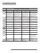
2.3 - Left Trigger Optimization Matrix DOT 2.
2.5 - Right Trigger Optimization Matrix DOT 2.
2.7 - Handle Optimization Matrix DOT 2.
2.9 - Continuous Trigger Optimization DOT 2.10 - Continuous Scan Scan the following codes to turn continuous scanning on/off: Both Near & Far Field On Near Field Only On Far Field Only On Off (Default) Note: This function is only recommended for cabled or short term use if battery is the only power supply. See section 7.4.
2.11 - Continuous Scan Settings 2.11.
Chapter 3 - CR3 Programming: Symbology Settings Save Settings C002332_09_CR3 User Manual - 32
3.1 - Introduction The following chapter will allow a user to change the symbology settings on the CR3. To reset the unit to factory defaults or to save the current settings please scan one of the codes below: Save Settings Reset to USB Factory Defaults Reset to PS2 Factory Defaults Bluetooth settings will not be erased.. Bluetooth settings will not be erased. Reset to RS232 Factory Defaults Reset to RF One Way Factory Defaults Clear All CodeXML Rules Bluetooth settings will not be erased.
3.4 - Codablock F Symbology Scan the following codes to enable/disable Codablock F symbology settings: Codablock F On Codablock F Off (Default) Sample Codablock F Code Note: When Codablock F and Code 128 decoding are enabled, there is some danger of mistakenly decoding a damaged Codablock F symbol as a Code 128 symbol. Therefore, Code 128 decoding should be disabled when Codablock F decoding is enabled. 3.
Code 39 Short Margin On Code 39 Short Margin Off (Default) Code 39 Trioptic On Code 39 Trioptic Off Sample Code 39 Code Sample Trioptic Code 39 3.7 - Code 93 Symbology Scan the following codes to enable/disable Code 93 symbology settings: Code 93 On (Default) Code 93 Off Sample Code 93 Code 3.
3.9 - Composite Symbologies Scan the following codes to enable/disable Composite symbology settings: Composite On Composite Off (Default) 3.10 - Data Matrix Symbology Scan the following codes to enable/disable Data Matrix symbology settings: Data Matrix Rectangle On Data Matrix Rectangle Off (Default) Data Matrix Inverse On Data Matrix Inverse Off (Default) Sample Data Matrix Code Sample Data Matrix Code 3.11 - GoCode Symbology GoCode is a miniature, two-dimensional (2-D) symbol.
3.12 - Interleaved 2 of 5 Symbology Scan the following codes to enable/disable Interleaved 2 of 5 symbology settings: Int 2 of 5 On (Default) Int 2 of 5 Off Int 2 of 5 Two Digits On Int 2 of 5 Two Digits Off Int 2 of 5 Four Digits On Int 2 of 5 Four Digits Off Sample Int 2 of 5 Code 3.
3.14 - Matrix 2 of 5 Symbology Scan the following codes to enable/disable Matrix 2 of 5 symbology settings: Matrix 2 of 5 On Matrix 2 of 5 Off (Default) Matrix 2 of 5 Sample 3.15 - Micro PDF417 Symbology Scan the following codes to enable/disable micro PDF 417 symbology settings: MicroPDF417 On MicroPDF417 Off (Default) Sample MicroPDF417 3.
3.17 - NEC 2 of 5 Symbology Scan the following codes to enable/disable NEC 2 of 5 symbology settings: NEC 2 of 5 On NEC 2 of 5 Off (Default) 3.
3.19 - Pharmacode For an explanation of Pharmacode settings and all programming codes please refer to Appendix G of the CR3 User Manual. You may download the Appendix G at: www.codecorp.com/support/usermanuals.htm 3.20 - Postal Symbologies All postal code default settings are OFF. Scan the following codes to enable the appropriate Postal symbology: Note: If you wish to change which Postal code is activated, you MUST first scan the disable all postal codes symbol and then scan your desired symbology.
3.21 - QR Code Symbology Scan the following codes to enable/disable QR Code symbology settings: QR Code On QR Code Off (Default) Enable Checksum Disable Checksum (Default) QR Code Inverse On Both Inverse and Standard On All QR On (includes Micro QR) Inverse QR and Micro QR On Sample QR Code Sample Micro QR 3.
Sample RSS Limited Code Sample RSS 14 Code Sample RSS 14 Truncated Code Sample RSS 14 Stacked Code 3.23 - Telepen Symbology Scan the following codes to enable/disable Telepen symbology settings: Telepen On - Default Telepen Off Sample Telepen 3.
Chapter 4 - Reader Feedback and Special Settings Save Settings C002332_09_CR3 User Manual - 43
4.1 - Volume and Vibration Settings Scan the following codes to set vibration mode: Vibrate On / Beep On Vibrate On / Beep Off Vibrate Off / Beep On (Default) Scan the following codes to set your reader’s volume: Beep Off Beep Low Beep High (Default) Scan the following codes to set the volume for keypad button press sounds: Off (Default) Low Medium High 4.2 - Code Readability Index The Readability Index provides a measurement of a specific symbol’s ease or difficulty to be decoded by the CR3.
The Readability Index is enabled by first reading a CodeXML rule into the permanent CR3 Memory: Code Readability Index Rule: The reader will store the rule and reset, but will not output the Readability Index until the Readability Index Output Enable code is read. Readability Index Output Enable: Each time a data symbol is read, the index will be output, followed by a comma, (,) followed by the decoded data.
4.4 - Backlight Timeout Settings Scan the following codes to set the backlight settings: Backlight Off 3 seconds (Default) 6 seconds 10 seconds 4.5 - Laser Settings Scan the following codes to turn laser targeting on/off: On (Default) Off Scan one of the following codes to set the brightness of the CR3 laser. High (Default) Medium Low 4.
4.7 - Reader ID and Firmware Version To find out the Reader ID and firmware version, open a text editor program (i.e., Notepad, Microsoft Word, etc.) and read the following code: Reader ID and Firmware Note: For units with a Bluetooth Radio, the Reader ID is also your Bluetooth Radio PIN #.
4.9 - Keyboard Support Scan the following codes to set appropriate keyboard mapping: US English (Default) No Leading 0 US English - Leading 0 US English - ctrl + char French German Japanese Universal Keyboard Custom Keyboard Requests map to be installed 4.10 - Time Stamp Settings CR3 has a battery-powered real time clock embedded in the reader. When enabled, the time stamp will be a prefix to the data. Time stamping continues until disabled.
4.11 - Lock-out Link Mode To establish a permanently linked connection between the reader and a CodeXML modem, you must first scan the Reader ID and Firmware Version code (see below). Verify the modem is connected to the host and the Blue LED is on. (Note: Verify reader contains a radio by locating the ‘XXXX’ number - see Section 4.7. If there is no number indicated, the reader does not contain a radio.
Chapter 5 - Advanced Decode Performance Save Settings C002332_09_CR3 User Manual - 50
5.1 - Continuous Illumination Scan one of the following codes to enable continuous LED illumination. Enable Continuous Illumination Disable Continuous Illumination (Default) Note: Code recommends only using this feature with cabled units due to increased power consumption. 5.2 - Set Targeting Zone Tolerances The targeting zone is the area around the outside of the code that is viewed by the imager.
5.3 - Windowing If only one size of bar code is being scanned in an application, the CR3 can be optimized to reduce processing time by adjusting the viewing frame within the field of view of the image (ONLY FOR SXGA MODE). By reducing the vertical window value of the imager to 200 pixels, 1-D codes are processed more quickly. Because only a horizontal strip of a 1-D code is needed to be decoded, using a narrow strip of the imager is all that is needed.
Users may optimize the CR3 decode zone if their application only requires one bar code format. If the size and density of the bar codes to be scanned are consistent, please select the setting below that best describes your environment (ONLY FOR SXGA MODE). 1-Dimensional Codes ONLY (1024 X 200 pixels) Caution: It may be more difficult to read other codes while in this setting. You must have the reader farther away than normal.
5.4 - VGA & Megapixel Settings User’s may optimize the CR3’s megapixel (SXGA) imager (1280 x 1024) to VGA (640 x 480). This feature is used to decrease the pixel sampling area, which will greatly increase processing speed. This is an advanced feature used for the rapid decoding of 1-dimensional/linear codes and larger module size 2dimensional codes. Code recommends testing this feature, as it will not work well with many high density codes.
Chapter 6 - Adding a Prefix or Suffix and Reader Text Commands Save Settings C002332_09_CR3 User Manual - 55
6.1 - Prefix Settings If you scan the following codes, you will lose any unsaved settings. Make sure to save settings on your reader before scanning the prefix codes. If you scan more than one prefix you will receive each scanned prefix in your scanned data; (i.e., if you scan comma prefix twice, you will get two comma prefixes).
Suffix - Tab Suffix - Tab Only Use with USB Keyboard, PS2 Keyboard Mode or with CodeXML Router or PS2 CodeXML Bluetooth Modem Suffix - Erase / None This code will erase all suffix data. Only Use with Serial Application 6.3 - Erase Prefix and Suffix Settings Scan the following codes to erase all prefix and suffix data. Erase Prefix & Suffix Data 6.4 - Reader Text Commands Enabling Reader Text Commands allows the CR3 to accept text commands via RS232 or RF commmunication.
Chapter 7 - CR3: Maintenance and Troubleshooting Save Settings C002332_09_CR3 User Manual - 58
7.1 - Reset Reader to Factory Defaults Scan the following codes to reset reader: Reset to USB Factory Default Settings Reset to PS/2 Factory Default Settings Radio settings will not be reset with this code. Radio settings will not be reset with this code. Radio settings will not be reset with this code. Reset to RF One Way Factory Default Settings Reset to RS232 Factory Default Settings Bootloader Mode Bootloader mode is utilized to download new version of bootloader firmware and custom applications.
Lithium Ion Battery - Warning: Charge the battery with Code cables ONLY. Do not open battery, dispose of in fire, or short circuit - it may ignite, explode, leak, or get hot causing personal injury. 7.3 - Warranty Code Corporation’s Code Reader 3.0 carries a two year limited warranty as described herein. Customers may purchase a one or two year extension to this warranty. Please contact a Code representative for more information.
products. Customer will pay for any pre-shipped replacement product in case it does not return the replaced product to Code within 7 days of receipt of the replacement product. The process for return and customer’s charges will be in accordance with Code’s Exchange Policy in effect at the time of the exchange. Customer accepts full responsibility for its software and data including the appropriate backup thereof. Repair or replacement of a product during warranty will not extend the original warranty term.
7.5 - Frequently Asked Questions For a complete list of Frequently Asked Questions, please visit: http://www.codecorp.com/support/faq.htm 7.6 - CR3 Maintenance The CR3 device operates efficiently and reliably and needs only a minimum of maintenance to operate. A few tips are given below for maintenance suggestions. Cleaning the CR3 Window The CR3 window should be clean to allow the best performance of the device. The window is the clear plastic piece inside the head of the reader. Do not touch the window.