
Installation guide


128-6531
7 of 24
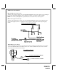
Purple: (+) Door Trigger Input
If the vehicle's door courtesy light switches + 12 volts when the door is opened, (Some Ford and some
Import), you must connect this wire to the positive output from one of the vehicle's door pin switches. In most
cases, the Purple wire will need to be connected to only one door switch no matter how many doors the
vehicle has as most door lighting circuits are wired in parallel.
Note for vehicles with interior delay lighting see programming under title "Completing The Installation".
Green: (-) Door Trigger Input
If the vehicle's door courtesy light switches to Ground when the door is opened, you must connect this wire
to the negative output from one of the vehicle's door pin switches. In most cases, the Dark Green wire will
need to be connected to only one door switch no matter how many doors the vehicle has as most door
lighting circuits are wired in parallel.
Note for vehicles with interior delay lighting see programming under title "Completing The Installation".
7
BLUE w/BLACK: Active output
This wire provides a 300mA ground output that becomes active 3 seconds before the Remote Start system
initializes, and remains grounded while running plus an additional 4 seconds after the Remote Start system
turns off. In all of the applications described below, a relay will be required. The Blue/Black wire can be used
to accommodate the following situations:
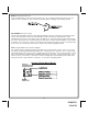
1. Ignition 3 Output:
Some newer vehicles use a third ignition wire which is required to start and keep the vehicle's engine
running. If this is the case, connect the Blue/Black wire to terminal #86 of an external relay. Connect terminal
# 30 & # 85 to a fused + 12 volt battery source rated for a minimum of 25 Amp. Connect terminal # 87 to the
third ignition wire in the vehicle.
2. Transponder Key Override:
To bypass the system while the vehicle is operating under the control of the Remote Start system. Connect the
Blue/Black wire to the NEG trigger input of the accessory bypass.
BLACK/GRAY: Diesel Wait To Start
For Diesel glow plug preheat circuits, this Wait To Start input will allow the ignition to keep the glow plugs
active for the vehicles automatic time out period before cranking the starter motor. If the BLK/GRY is connected
to the glow plug wire, this will take precedence over the timing setting and the Gas/Diesel programming in the
feature programming chart. Use this wire if you do not want to set the timing of the glow plug preheat circuit as
shown in the feature programming chart.