
Installation guide


128-6531
4 of 24
4
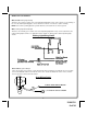
WIRING THE 6 PIN HARNESS:
RED w/ VIOLET: +12 volts
Connect this wire to a +12 Volt constant source found at the vehicle's ignition switch using the 30 Amp fuse and
holder provided. This wire provides power for the control circuit as well as the ignition 1 and ignition 2 relays.
RED: +12 Volts
Connect this wire to a +12 Volt constant source found at the vehicle's ignition switch using the 30 Amp fuse and
holder provided, but NOT the same vehicle wire as used by the Red/Violet wire above. Most vehicles have more
than one battery source supplying power to the ignition switch. Separate feed wires must be used for the Red
and Red/Violet wires. If your vehicle does not have two battery feed wires at the ignition switch then it is possible
to connect both wires to the vehicle's battery. This wire provides power for the start relay and the accessory relay.
IMPORTANT!
It is the responsibility of the installing technician to determine the load factor of the vehicles electrical circuits
when the vehicle is running and to adequately fuse the two power wires based on that load.
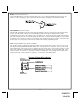
VIOLET: Starter Output
This wire will have +12 volts when the ignition switch is turned to the START (crank) position only. This wire will
have 0 volts in all other ignition switch positions.
PINK: Ignition 1 Output
Connect this wire to the ignition 1 wire from the ignition switch. This wire will show +12 volts when the ignition key
is turned to the to the ON, RUN and START positions, and will have 0 volts when the key is turned to the OFF and
ACCESSORY positions. For Diesel Applications, this wire must be connected to the ignition circuit that powers
the glow plugs if the vehicle requires glow plug pre-heating. (See selectable feature #8)
PINK w/ WHITE: Ignition 2 Output
Connect this wire to the ignition 2 wire from the ignition switch. This wire will show + 12 volts when the ignition
key is turned to the ON or RUN position and is some cases the START position. This wire will show 0 volts when
the key is turned to the OFF and ACCESSORY positions.
NOTE: See programming information concerning this wire to function as a ACCESSORY wire.
ORANGE: Accessory Output
Connect this wire to the Accessory wire from the ignition switch. This wire will show + 12 volts when the ignition
switch is turned to the ACCESSORY, ON and RUN positions, and will show 0 volts when the key is turned to the
OFF and START positions.