
Installation guide
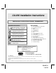


128-6531
3 of 24
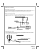
This will prevent the antenna from dropping down in case the double stick tape is exposed to extreme heat,
which may loosen its gummed surface. Route the 3 pin connector toward the control module using caution not to
pinch the cable as this will cause poor or no RF reception to the control module.
VALET/PROGRAM/MANUAL OVERRIDE SWITCH :
Select a mounting location that is easily accessible to the operator of the vehicle. It is not necessary to conceal
the switch. However, concealment is recommended as it offers a higher level of security. The switch can be
mounted to the lower dash panel in the driver's area. Inspect behind the chosen location to insure that adequate
clearance is allowed for the body of the switch, and also that the drill will not penetrate any existing factory wiring
or fluid lines. Drill a 5/32" hole in the desired location and mount the switch by passing it through the panel from
the underside. Secure the switch using the nut and star washer. Route the switch's connector toward the control
module.
NOTE: During the program sequence, there are times when this switch and the ignition switch will be used
simultaneously. We recommend that the push-button switch be mounted on the left side of the ignition switch to
facilitate this operation.
SAFETY (Red Handled ) CONTROL SWITCH:
Select a mounting location that is within reach of the ignition switch, as this switch, in combination with the
ignition switch and brake, will be used to program the certain features of the system. It is suggested that the
switch be mounted to the lower dash panel in the driver's area. Inspect behind the chosen location to insure that
adequate clearance is allowed for the body of the switch, and also that the drill will not penetrate any existing
factory wiring or fluid lines. Drill a 1/4" hole in the desired location and mount the switch by passing it through
the panel from the underside. Secure the switch using the nut, star washer, and ON/OFF face plate. It is best to
install the switch to allow the ON position to be up toward the driver and the OFF position to be down or away
from the driver. Route the switch wires toward the control module.
SHOCK SENSOR:
Select a centrally located, solid mounting surface for the shock sensor that will allow consistent operation from
all areas of the vehicle. The selected location must be within 18" of the control module to allow routing and
connecting of the 4 pin harness. Secure the shock sensor to the chosen location using two #8 self taping sheet
metal screws. The sensor can also be secured to an existing dash brace using cable tie straps. Whichever
mounting method is used be sure to allow access to the sensitivity adjustment potentiometer for use later in the
installation.
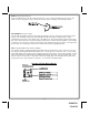
STARTER KILL RELAY:
Select a mounting location within 12" of the ignition switch's low current start solenoid wire. Secure the relay to
an existing harness in the chosen location using a cable tie around the relay's wiring harness. Caution! Do not
wire tie the metal bracket to an existing wiring harness as vibration may cause chaffing and shorting damaging
the factory wiring. If an existing harness is not available then secure the relay's metal mounting tab to an under
dash metal brace with a #8 self taping sheet metal screw. Wire the relay as per the diagram found later in this
manual. The CA-610 is to be used in vehicles with AUTOMATIC TRANSMISSIONS only! Although this is a
sophisticated system with many advanced features, IT MUST NOT be installed into a vehicle with a manually
operated transmission. Doing so may result in serious personal injury and property damage.
3