
Installation guide
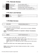

7
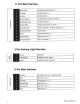
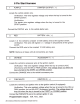
BLUE/BLACK
START STATUS
I
ACTIVE
OUTPUT
(-)
This wire provides a ground output when the remote start function is activated
and remains until 4 seconds after the remote start is shutdown. If
this wire
will
be used for multiple application's a
1 amp diode is required in-line with the stripe
facing the control module.
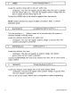
8
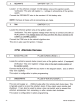
PURPLE/WHITE
TACH
INPUT
Locate the vehicle's ignition coil or fuel injector in the engine compartment.
Verification:
Test using the
following
procedure:
1.
Set voltmeter to
AC
VOLTS.
2.
Attach positive lead of a volt meter to a constant 12-volt source.
3.
Attach negative
lead
of a volt meter
to the wire to be tested.
4.
Start
the engine.
5. Have someone press
on
the gas pedal slightly as you monitor the meter. If
connected to the correct wire, the voltage reading
will
increase as the engine's
RPM increases.
Connect the
PURPLE/WHITE wire to the negative side of the vehicle ignition coil
or
fuel injector.
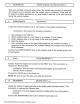
9
GRAY
HOOD
PIN
INPUT
(-)
Install a Hood Pin
Switch and connect to the GRAY wire. This connection is
required for Remote
Start.
Verification:
This wire when connected
will
register ground when the
vehicle's hood is opened.
Connect the GRAY wire to the hood pin.
NOTE:
Be
sure to loom the wire, and seal the grommet.
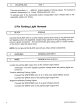
1
0
BROWN/RED
BRAKE INPUT
(
+)
Locate the vehicle's brake light wire at the brake pedal mounted switch. This
connection is required for Remote
Start.
Verification:
This wire registers positive voltage when the brake pedal is
pressed.
Connect the BROWN/RED wire to the vehicle's brake light wire.
2012
Audiovox
Electronics
Corporation.
All
rights
reserved.
7