cc c c: W-~1./.1 ~ m r:»~OFESSIONAI SE~IES Automatic I Manual Transmission Remote Start with Keyless Entry Installation Guide for models: ca5153 ca5153sst 2012 Audiovox Electronics Corporation. All rights reserved.
Table of Contents Before You Begin ...................................................................................... 3 Wire Connection Guide ........................................................................... 4 11 Pin Main Harness ................................................................................. 5 3 Pin Parking Light Harness ..................................................................... 8 6 Pin Start Harness ...............................................................
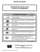
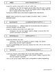
BEFORE YOU BEGIN PROFESSIONAL INSTALLATION STRONGLY RECOMMENDED Roll down window to avoid locking keys in vehicle during installation Avoid mounting components or routing wires near hot surfaces Avoid mounting components or routing wires near moving parts Use a Digital Multi Meter for testing and verifying circuits. DO NOT USE A TEST LIGHT, OR "COMPUTER SAFE PROBE" as these can set off air bags or damage vehicle computers. Technical Support ..•.. (SOO) 421-3209 or go to http://techser vices.
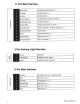
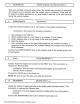
11 Pin Main Harness GRAY/RED PARKING BRAKE INPUT (- ) PURPLE DOOR INPUT ( +) GREEN DOOR INPUT (-) BLACK/WHITE ILLUMINATED ENTRY OUTPUT ( - ) BROWN/BLACK HORN OUTPUT ( - ) z RED/WHITE TRUNK RELEASE OUTPUT (-) .,...- BLUE/BLACK START STATUS I ACTIVE OUTPUT ( - ) PURPLE/WHITE TACH INPUT GRAY HOOD PIN INPUT (-) BROWN/RED BRAKE INPUT ( + ) VIOLET/BLACK AUX 1 OUTPUT ( - ) z <( ~ a.. .,...- 3 Pin Parking Light Harness C/) ZI-I a..
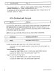
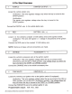
4 Pin Alternate Harness BLACK/YELLOW PULSE DURING CRANK (-) GREEN/WHITE PULSE AFTER SHUIDOWN (-) LT BLUE FACTORY ARM I PULSE AFTER START ( - ) LT GREEN/BLACK FACTORY DISARM I PULSE BEFORE START ( - ) 2 Pin Door Lock Harness z~ -u o...o N_.J BLUE UNLOCK (-) GREEN LOCK (-) 11 Pin Main Harness 1 GRAY/RED PARKING BRAKE INPUT (-) Locate the vehicle's parking brake wire. Verification: This wire will register ground when the vehicle's PARKING BRAKE is engaged.
3 GREEN DOOR TRIGGER INPUT (- ) Locate the vehicle's dome light or door pin switch wire. Verification: This wire will register ground (NEG) when the door is opened and the interior light is on. This wire will register positive voltage when the door is closed and the interior light is off. Connect the GREEN wire to the vehicle's negative door input wire(s). NOTE: Certain vehicles may require multiple connections. Refer to vehicle application guide.
BLUE/BLACK START STATUS I ACTIVE OUTPUT (-) This wire provides a ground output when the remote start function is activated and remains until 4 seconds after the remote start is shutdown. If this wire will be used for multiple application's a 1 amp diode is required in-line with the stripe facing the control module. 8 PURPLE/WHITE TACH INPUT Locate the vehicle's ignition coil or fuel injector in the engine compartment. Verification: Test using the following procedure: 1. 2. 3. 4. 5.
11 VIOLET/BLACK AUX 1 This wire provides a ( - ) SOOmA output capable of driving relays. For Control of optional accessorie s (i.e. Power Window/Su nroof, etc.). To activate refer to the transmitter button configuration chart. Please refer to the selectable options for timing. 3 Pin Parking Light Harness 1 BLACK GROUND Connect the BLACK wire to a solid chassis ground point using a ring terminal and self tapping screw (not supplied).
6 Pin Start Harness 1 PURPLE STARTER OUTPUT ( + ) Locate the vehicle starter wire. Verification: This wire registers voltage only when the key is turned to the START position. Verification: The starter wire registers voltage when the key is turned to the START position. Connect the PURPLE wire to the vehicle starter wire. 2 RED BATTERY 12V ( + ) Locate 1 of the vehicle's constant 12 Volt battery wires at the ignition switch.
5 RED!WHITE BATTERY 12V ( + ) Locate 1 of the vehicle's constant 12 Volt battery wires at the ignition switch. Verification: This wire will register ( +) voltage in all positions of the ignition switch. Connect the RED/WHITE wire to the constant 12 Volt battery wire. NOTE: Remove all fuses until all connections are made. 6 PINK IGNITION 1 ( +) Locate the vehicle's ignition wire at the ignition switch. Verification: This wire registers voltage when the key is turned to the ON (or RUN) position.
3 LTBLUE FACTORY ARM I PULSE AFTER START (-) This wire will supply a (-) 500mA pulse both upon arming the system and upon successful completion of the remote start activation sequence and is typically used to re-lock the vehicle's doors upon remote start if necessary. This output is configurable in option programming. 4 LT GREEN/BLACK FACTORY DISARM I PULSE BEFORE START (-) This wire will supply a ( - ) 500mA pulse both upon disarming the system and when the remote start feature is activated.
Negative Switching Locks All Door Lock and Unlock: Locate the lock I unlock wire at the vehicle's lock I unlock switch. Verification: These wires will register ground when the Lock and Unlock switches are activated. Connect the GREEN and BLUE wires shown in the diagram below. Negative Locks: GREEN(-) Lock Output Vehicle Door Lock Control Relays BLUE (-) Unlock Output Positive Switching Locks All Door Lock and Unlock: Locate the lock I unlock wire at the vehicle's lock I unlock switch.
Reverse Polarity Locks (S-Wire Door locks) All Door Lock and Unlock: Locate the lock I unlock wire at the vehicle's lock I unlock switch. Verification: These wires will rest at ground and register positive voltage when the Lock and Unlock switches are activated. Connect the GREEN and BLUE or BLUE/GREEN wires shown in the diagram below using (2) SPOT relays (not supplied). Reverse Polarity Locks: GREEN(-) Lock Output BLUE(-) Unlock Output -..
Positive Multiplexed Locks All Door Lock and Unlock: Locate the lock I unlock wire at the vehicle's lock I unlock switch. Verification: This wire will show variable positive voltage when the switch is activated. Please consult the wire and location chart for specific resistor values for your vehicle. Connect the GREEN and BLUE or BLUE/GREEN wires shown in the diagram below using (2) SPOT relays (not supplied).
Additional :Ports Antenna I LED I Programming Port Mount the supplied antenna/receiver to a clear spot on the vehicle's windshield that will not block the driver's vision. A good location is usually high on the windshield near the rear view mirror. Be careful not to mount the antenna/receiver on any metallic window film, as this will effect system range. Route the antenna/ receiver cable to the control module and plug into the antenna port.
Set Up & Programming Transmitter Programming - Feature Bank 1 1. Turn the ignition ON. 2. Press and hold the valet/override button. Within 10 seconds the system will chirp (3) three times. Press 1 button of each transmitter you wish to program. The system will respond with 1 chirp for each accepted transmitter. Pressing the override button at anytime during programming will advance to the next bank. 3. 4. 5. 6. NOTE: The system will exit transmitter programming after 15 seconds of inactivity.
Feature Bank 1 - 3 Chirps Transmitter Programming Refer to transmitter programming. Factory Disarm 2 Lt Green I Black Factory Disarm Factory Disarm I Start Status NOTE: On this model the Lt Green I Black Output wire can be configured in Bank 3 or Bank 5. Any changes to this feature in Bank 5 will override changes made in Bank 3. 2012 Audiovox Electronics Corporation. All rights reserved.
Feature Bank 5 • 7 Chirps 4 Pin Alternate Output Control 4 Black I Yellow Output Pulse During Crank Ground While Running Ignition NOTE: On this model the Lt Green I Black Output wire can be configured in Bank 3 or Bank 5. Any changes to this feature In Bank 5 will override changes made in Bank 3.
Tach Programming The unit will not operate unless a tach signal is programmed or the tachless option is turned ON. If an attempt is made to start the vehicle via the remote start without first programming tach, the unit will flash the parking lights 7 times indicating tach has not been learned and stored. If the tach rate is not properly programmed to the specific vehicle, the unit may not realize that the vehicle is running in certain instances and reengage the starter motor.
Feature Descriptio ns Feature Bank 2 - Security 1 - Silent Choice: Controls the normal arm/disarm chirps of the security system. ON - Silent arming/disarming upon first press of lock/unlock, pressing lock/ unlock a second time will activate the arm/disarm chirps respectively. The system will only sound the arm/disarm chirps upon a second press of the lock/unlock buttons. OFF - normal arm/disarm chirps upon the first press of lock/unlock. 2 - 8 Not available on this model.
2 - Factory Disarm: Controls the timing of the LT. GREEN/BLACK factory disarm output. Factory Disarm - Single 1 second pulse with unlock and remote start activation. 2nd Unlock- Same output as unlock with 2nd press of unlock. Start Status - Single 1 second pulse with unlock and continuous ( - ) output during the remote start cycle. NOTE: On this model the Lt Green I Black Output wire can be configured in Bank 3 or Bank 5. Any changes to this feature in Bank 5 will override changes made in Bank 3.
7- AUX 1: Controls the VIOLET/BLACK AUX 1 output activation type and timing. Push and Hold - Output is continuously active until transmitter button is released. Latched - Output stays active until button is pressed again. Latched until IGN ON - Output stays active until the ignition is turned on. Dome Light Output - Output used for illuminated entry and is not controlled by the AUX 1 function of the transmitter.
5 - Voltage Level: The voltage variance for remote start when set to tachless. (see tach mode) HIGH -The variance in battery voltage from before the remote start is activated to after the engine is running must be greater than 0.5 volts. LOW - The variance in battery voltage from before the remote start is activated to after the engine is running may be less than 0.5 volts. 6 - Crank Time: Preset output times for the PURPLE starter wire. 1 Second 0.8 Seconds 1.
12 - Turbo Timer: Not available on this model. 13 - Transmission Mode: Select the type of remote start activation based on the vehicle's transmission type. Automatic - For use with automatic transmission vehicles. Standard remote start operation. Manual - For use with manual transmission vehicles. Remote start ready mode must be set upon exit of vehicle to enable remote start. Feature Bank 5-4 Pin Alternate Output Control 1 - Black/Yellow Output : Controls the BLACKNELLOW output activation type and timing.
4- Lt Green/Black Output : Controls the LT GREEN/BLACK output activation type and timing. Pulse before Start I During Unlock- 1 second pulse when remote start is activated. Also a 1 second pulse when unlock is pressed. Ground While Running - Continuous output for the entire remote start sequence until after the vehicle shuts down. Ignition - Output becomes active with the same timing as the ignition output and does not drop out during crank.
Transmitter Button Functions 1 Way Tra nsm itte r AUX 1 26 Lock Unlock X X Car Find I Panic Start Operation Method Push and Hold (3 Sec) ca5153 I 5153sst rev A
If the remote start shuts down or fails to start, the parking lights will flash one of the patterns below indicating the shutdown input. To manually enter diagnostics and view the last shutdown, turn the ignition ON and press and release the ._. button.
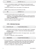
1\) (X) BLUE GREEN UNLOCK (-) LOCK (-) BLACK/YELLOW GREEN/WHITE LT BLUE LT GREEN/BLACK PULSE DURING CRANK ( - ) PULSE AFTER SHUTDOWN ( - ) FACTORY ARM I PULSE AFTER START ( - ) FACTORY DISARM I PULSE BEFORE START ( - ) D BLACK WHITE/RED WHITE E~ n:~ :s~ ~~ o;; IU u; 0~ ULO GRAY/RED PURPLE GREEN BLACK/WHITE BROWN/BLACK RED/WHITE BLUE/BLACK PURPLE/WHITE GRAY BROWN/RED VIOLET/BLACK GROUND PARKING LIGHT INPUT PARKING LIGHT OUTPUT PARKING BRAKE INPUT ( - ) DOOR INPUT ( + ) DOOR INPUT ( - ) ILLUMINA
2012 Audiovox Electronics Corporation. All rights reserved.
Audiovox Electronics Corporation. Customer Service 1-800-421-3209 WWW.CODE-ALARM.COM FCC COMPLIANCE This device complies with Part 15 of the FCC rules and with RSS-21 0 of Industry Canada. Operation is subject to the following two conditions: 1. This device may not cause harmful interference, and 2. This device must accept any interference received, including any interference that may cause undesired operation.
CCCc~l./.l~m Automatic I Manual Transmissi on Remote Start and Keyless Entry System IMPORTANT NOTE: The operation of the Security and Convenience System as described in this manual is applicable to most vehicles. However, due to the configuration of some vehicles, some functions AND/OR SAFETY PRECAUTIONS may not apply. Please see your installing dealer for more information. 2012 Audiovox Electronics Corporation. All rights reserved.
Table of Contents Using Your Remote Control ............................................................... 3 Using the Keyless Entry ................................................................... 3 Two Stage Door Unlock (optional) ................................................... 3 Activating Trunk Release (optional) ................................................ 3 Activating AUX 1 (optional) ..............................................................
Using Your Remote Control Using the Keyless Entry The @ button is used to lock the vehicle's doors, the ri] button is used to unlock the vehicle's doors. To lock or unlock the doors simply press and release the desired function button one time. For your convenience, the parking lights will flash once when the doors are unlocked and twice when the door are locked. NOTE: The system is equipped with a feature called Silent Choice.
Programmed Transmitter Notification As a security precaution each time the vehicle's ignition is turn on the status LED light with flash the number of transmitters programmed into the system. This helps to identify unauthorized transmitters from accessing your vehicle. If you believe an unauthorized transmitter has been programmed to your system, contact your installing dealer for assistance. Valet Mode Valet Mode is used to disable the system from remote starting.
Using Your Remote Starter Remote Start Ready Mode must be enabled if your vehicle is equipped with a manual transmission. Remote Start Ready Mode - Manual Transmission Vehicles Only To activate the remote start function, the system must first be in Remote Start Ready Mode. Follow the steps below to enter remote start ready mode. 1. While the engine is running by the ignition key; a. Set the parking brake b. Place the transmission in neutral. 2.
Remote Starting Your Vehicle To activate the remote start function, press and release the 0 button 2 times within 2 seconds. The system will sound, the parking lights will flash 1 time and the system will check the vehicle to ensure it is safe to start. If all safety parameters are correct, the vehicle will start within 5 seconds. The vehicle's parking lights will turn on (or flash depending on system settings) as a visual indication that the vehicle has started and is running.
Using the "Quick-stop" Feature - Automatic Transmission Vehicles If you want to make a short stop and keep your vehicle running (to keep the interior warm or cool), the quick-stop feature allows you to do this while keeping your vehicle secure and your keys with you. To engage quick stop: 1. Stop the vehicle and place the transmission in PARK. 2. With your foot off the brake pedal, press and release the 0 button 2 times within 2 seconds. The LED will flash 3 times to confirm quick stop is entered. 3.
Transmitter Button Functions Replacing Remote Control Batteries 1-Way Remote Control (part # CATXMT) The batteries (model CR2016) inside each remote control should last approximately 1 year under normal use. When the batteries become weak you will notice the remote control range (the distance from the vehicle the remote control will work) deteriorate and the small LED on the remote control will dim. To replace the remote control batteries: 8 1.
Code Systems, Inc. Limited Lifetime Warranty Code Systems Inc.
This product is covered by one or more of the following U.S. Patents; Other Patents pending. 0407,034,0580,160,5,132,660, 5,157,375, 5,193,141, 5,245,694, 5~315,285, 5,334,969 5,349,931' 5,357,560, 5,381,128, 5,412,3711 5,467,070t 5,469,141,. 5,469.151' 5,506,568 5,532,670, 5,534,845, 5,563,576, 5,563,600, 5,572, 185, 5,602,535, 5,614,883, 5,617.819 5,646,591, 5,650,774, 5,656,868, 5,673,017, 5,656,997, 5,712.638, 5,783,988, 5,783.
Audiovox Electronics Corporation. Customer Service 1-800-421-3209 WWW.CODE-AL ARM.COM FCC COMPLIANCE This device complies with Part 15 of the FCC rules and with RSS-21 0 of Industry Canada. Operation is subject to the following two conditions: 1. This device may not cause harmful interference, and 2. This device must accept any interference received, including any interference that may cause undesired operation.
WARNING THIS VEHICLE IS EQUIPPED WITH A REMOTE CON TRO LLE D CAR STARTER BEFORE SERVICING THIS VEHICLE, REMOVE THE MAIN POW ER FUSE (RED WIRE) TO THE CAR STARTER OR DIS CON NEC T THE VEH ICLE BATTERY.