
Technical data


-10-
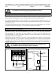
In case the transmitter is not operated on a GMA controller, the operational voltage of the mains unit
must not exceed 30 V DC.
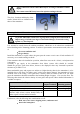
Fix the casing top with the four special screws after installation.
!
The user must make sure that even in case of failure the voltage at the
transmitter terminals does not exceed the max. fault voltage U
m
indicated on
the type label.
U
m
= 250 V AC resp. U
m
= 45 V DC
Putting in Operation
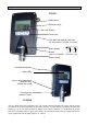
The transmitter CC28 has passed quality control for correct operation and display before delivery.
The calibration was carried out with the appropriate test gases. Depending on transport, mounting
and ambient conditions however variations may occur. Therefore the gas warning system has to be
taken into operation and function checked by the manufacturer or by a professional which is
authorized by the manufacturer, according to BGV B6 (former VBG61-gases), resp. BG Chemie
guideline T 023.
After having been turned on, the unit needs a few minutes for:
• the self-test, checking the program and the working memory,
• entering and evaluating of transmitter parameters with simultaneous memory check,
• entering and evaluating of sensor parameters with simultaneous memory check,
• warming-up the sensor.
Within 6 seconds during the warm-up period the transmitter checks the memory first. The current
interface provides 0 mA and both the yellow and the green LED are lit. Then the output signal turns
to 1.6 mA, the fault LED lights up and the operation LED flashes slowly. The display reads LoAd,
then AdJ. Once this is completed, the display of the CC28 D and CC28 DA resp. of the remote
control RC2 at the CC28 reads the unit, the type of gas, the detection range, the alarm thresholds and
the calibration gas concentration one after the other. If the automatic reset of the ambiguity alarm is
activated, this is indicated last, and the fault LED flashes rapidly.
Once the warm-up is completed after 2 minutes, the CC28 turns to detection mode automatically.
During this period the display reads a countdown of the seconds from 120.
If a fault is recognized during this time, the transmiter turns to fault mode. The current interface
provides 1.2 mA and the display indicates a fault message (SYS ERR.). The status and fault LEDs are
lit constantly. The alarm LEDs and the display illumination will flash alternately.
Once the sensor has been replaced after a sensor fault (SENS ERR.), the transmitter is automatically
re-started. In case of sensor replacement adhere to the safety notes for electrical connections in
explosion endangered areas (see page 7).
Note:
After the initial putting into operation resp. after a sensor replacement it might be possible that the
value falls below or exceeds the detection range (____ resp.
----
). In this case the zeropoint of the
transmitter must be corrected by starting the automatic zeropoint adjustment (ZERO).
Should SCAL ERR. occur (resettable), re-calibrate the sensor (SPAN) or, if necessary, enter the
service menu to adapt the detection range of the sensor to the hardware.
Allow a warm-up time of at least 30 minutes before you check the zeropoint. Once the warm-up is
completed, the display should read 0. Otherwise activate the (automatic) zeropoint adjustment
(AutoCal adjustment see page 11).