
Technical data


-9-
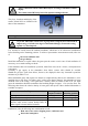
The transmitter is to a great extent protected against the ingress of water and dust (IP 64). Special
accessories are available to provide additional protection for very difficult conditions. Please contact
GfG for detailed information.
!
Warranty may be voided, if the sensor is exposed to ambient conditions which
were unknown to GfG during planning, production or delivery.
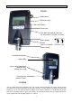
Mounting
When deciding on the position for the transmitter, make sure that it is always accessible for service
and maintenance. The transmitter must be mounted with the sensor showing to the floor.
For connecting the transmitter to the controller refer to the connection diagram (page 28). For
mounting the transmitter remove the four special screws and take the casing top off. Fix the casing by
means of two screws.
The printed circuit board inside the casing is potted in epoxy resin (encapsulation "m"). The side-
mounted terminals (increased safety “e”) are used for connecting the controller.
Installation of Electrical Connections
Procurement of cable and electrical connections must be done by a specialist only, obeying the
applicable regulations. Always use shielded cable (e.g. LIYCY 3 x 1.5 mm
2
). The cross section of the
cable depends on the cable length. For short distances up to 200 m it may be sufficient to use
0.75 mm
2
instead of 1.5 mm
2
. For longer distances the cross section must be 1.5 mm
2
. The cable
length must not be more than 1000 m.
The shield is fixed to the M16x1.5 screwing. In case the transmitter is mounted to an electrically
conductive background (e.g. steel grinder), a potential equalization is to be effected. If the transmitter
is installed in a room which is subject to Ex-regulations, make sure that only the transmitter is
installed in this area. The gas monitoring system resp. the mains supply and the controller must be
installed in the safe area.
!
The transmitter must be installed and opened in gas-free atmosphere only.
The transmitter must only be opened when de-energized.
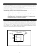
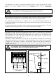
Terminal diagram
24V Ground 4..20mA
Potential equalization
Pot. equalization min. 4 mm
2
(at left side of casing)
Cable gland
Transmitter
Type label
Buzzer
Sensor
GMA Controller
e.g. steel
grinder
1 2 3 4