
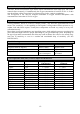
Technical data

-29-
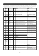
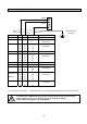
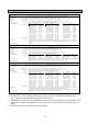
Connection Diagram CC 28 - with 4 .. 20 mA Output
24 V GND 4 – 20mA
GMA101 5 1 2
GMA100 5 1 2 with motherboard
from 1997
GMA104 55
58
61
64
53
56
59
62
54
57
60
63
connection to
multiplexer
GMA301 5 1 2
GMA304 55
58
61
64
53
56
59
62
54
57
60
63
connection to
multiplexer
GMA41 28 29 30
GMA81 (A) 1 2 3
GMA43 19
22
25
20
23
26
21
24
27
connection of up to 3
transmitters
GMA44 and
GMA84
19
22
25
28
20
23
26
29
21
24
27
30
connection of up to 4
transmitters
GMA88 19
:
40
20
:
41
21
:
42
connection of up to 8
transmitters
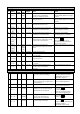
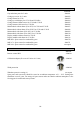
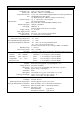
For connection to the GMA … controller please refer to the operation manual of the relevant GMA.
!
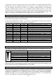
According to EN 50014 table 4 for devices of group II the casing has been tested
with an impact energy of 4 Joule (low degree of mechanical danger).
Protect the casing against very hard impacts.
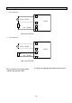
1
2
3
4
Shield laid on
screwing
brown
green
white