
Technical data

-25-
In detection mode the messages listed in the second column are indicated alternating with the
measurement value. The readings described in No.33 and 34 are only applicable for model CC28
DA. The readings described in No.35 and 36 are cautionary warning messages. The transmitter
remains in detection mode, and there is no immediate action required by the user. The status
described in No.32 and 38 refer to a de facto extension of the detection range from 4–20 mA to the
range 2.8–22 mA, for showing measurement values „close“ to the original detection range. This
generates a tolerance range around the 4–20 mA signal, before a special status occurs.
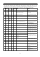
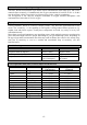
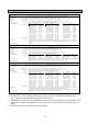
Situation of Status LED’s and Output
The following table shows for a transmitter without display the different indications of the two status
LEDs and the output signals with their meanings.
For the zeropoint adjustment (if display > 25 % LEL), for adjustments to enter the service menu on a
transmitter without display the remote control RC2 is obligatory.
green LED yellow LED Output Desription see chapter...
On On 2,8 mA Page 21 „Messages in detection mode“ No.39, 40
On On 1,2 mA P.21 „Messages in detection mode“ No.41
On On 0 mA P.21 „Special Status and relevant Error Messages“ No.01
On flashing quickly 22 mA P.21 „Messages in detection mode“ No.30, 31
On flashing quickly 2,0 mA P.21 „Messages in service mode...“ No.45-47
On Flashing slowly 2,4 mA P.21 „Messages in service mode...“ No.42
On Flashing slowly 2,0 mA P.21 „Messages in service mode...“ No.43, 44
On Single flashes 4–20mA P.21 „Messages in detection mode“ No.36
On Off 20–22mA P.21 „Messages in detection mode“ No.32
On Off 4–20mA P.21 „Messages in detection mode“ No.(33, 34), 35, 37
On Off 2,8–4mA P.21 „Messages in detection mode“ No.38
flashing On 1,6 mA P.21 „Special Status and relevant Error Messages“ No.02, 03
Twin flash On 1,2 mA P.21 „Special Status and relevant Error Messages“ No.12, 13
Single flash On 1,2 mA P.21 „Special Status and relevant Error Messages“ No.11
Off On 1,2 mA P.21 „Special Status and relevant Error Messages“ No.14-26
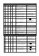
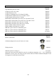
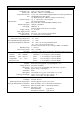
Priority of displays and messages in detection mode
The displays of situations with low priority will be substituted for displays with higher priorities (the
situations with low priority will not be deleted).
Priority Situation Description see chapter...
Ambiguity Page 22 „Messages in detection mode“ No.30, 31
A/D converter fault P.21 „Special Status and relevant …“ No.24-26
(minor) overrange P.22 „Messages in detection mode“ No.32
Alarm2 P.22 „Messages in detection mode“ No.33
Alarm1 P.22 „Messages in detection mode“ No.34
Detection range deviation P.22 „Messages in detection mode“ No.38-40
„SCAL-Error“ (Warning) P.22 „Messages in detection mode“ No.35
Sensor Replacement (Warning) P.22 „Messages in detection mode“ No.36
System- and sensor errors (P. 21, 22 No. 11 und No. 14-23) will interrupt the detection mode with its
messages. In case of a prior ambiguity alarm the status LEDs and the output will still indicate it and
the new special status will be indicated only by the LCD display.
Putting into Operation and Maintenance
Make sure that DIN EN 50073 „Guideline for choice, installation, use and maintenance of apparatus
for detection and measurement of combustible gases or oxygen“ as well as the relevant national
regulations are adhered to. For Germany this means the "Explosion Protection Regulations",
guideline T023 (BGI 518) „Gas warning Apparatus for Explosion Protection – Use and Operation“
and UVV-Gase BGV B6 „Accident Prevention Regulations Gases“.