
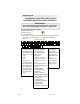
Programming instructions

6
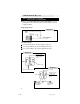
Ground for negative
polarity system
+12v fused for
positive polarity
system
+12v fused
To vehicle door lock module
24/B
Diagram 8
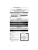
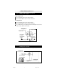
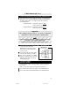
Type 5: Resistor Door Lock system
Polarity Fuse = Positive/Negative
Note: Refer to Vehicle Wire Color and Location Chart for correct
polarity. Move the fuse inside of the control module to positive or
negative polarity.
Single Stage Unlock
Two-Stage Unlock
Connect the 2/B wire as shown in Diagram 7 (above).
Connect the 24/B wire as shown in Diagram 8 (below).
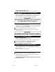
Connect the 14/B wire as shown in Diagram 9 (below).
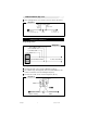
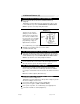
1. Basic Harness (B), cont’d
Diagram 7
14/B
Ground for positive
polarity system
+12v fused for
negative polarity
system
+12v fused
Cut
Diagram 9
From Switch
Side of Driver’s
Door Unlock
To Driver’s
Door Unlock
Motor
CA-640.p65 10/20/03, 7:47 PM6