
Programming instructions

11
12/A Aux - 3 500ma (20 AWG - ) (GRN/WHT)
This wire provides a 500ma negative output capable of driving
relays. For control of optional accessories (i.e.: power window/
sunroof, etc.)
13/A Aux - 4 500ma (20 AWG - ) (YELLOW/GREEN)
This wire provides a 500ma negative output capable of driving
relays for control of optional accessories (i.e.: power window/
sunroof, etc.)
2. Advanced Harness (A), cont’d
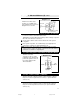
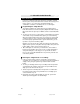
10/A Headlight
wire or
11/A defrost
wire
+12v fused
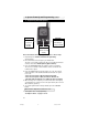
Diagram 11.5
To vehicle headlight
or defrost wire
10/A Cont. Headlight / Aux 1 500ma (20 AWG -) (RED/WHITE)
If wire in the vehicle tests
positive, use a SPDT relay
(not Supplied) and connect as
diagram 11.5 as shown
11/A Rear Defrost Output/Aux 2 500ma (20 AWG -) (BLU/WHITE)
Locate the vehicle rear window defrost wire.
Verification: This wire will register either positive voltage or ground
when the rear defroster is turned on.
Connect the 11/A wire to the vehicle defrost wire if the system
is negative.
If the system is positive, use a SPDT relay (not supplied) and
connect the 11/A wire as shown (Diagram 11.5).
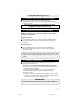
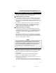
NOTE: If using Turbo Timer feature, the 11/A Aux 2 wire is used to
control a relay to power the Ignition 1 wire when the Turbo Timer is
activated. See below for relay diagram.
This wire is used to
energize a relay as shown
in diagram 11.6 (below) that
powers the Ignition 1 wire in
the vehicle during Turbo
Timer activation.
To 7/B
Ignition 1
Input/Output
To Second
Ignition /
Heater Wire
12V+
Constant
Diagram 11.6
11/A
Aux 2
12V+ Constant
To 7/B Ignition1
Input/Output
11/A Turbo Timer Ignition 1 Output 500ma (20 AWG)(BLU/WHITE)
CA-640.p65 10/20/03, 7:47 PM11