
User`s manual


Table Of Contents
- 535 User's Manual
- Table of Contents
- Chapter 1: Introduction
- Chapter 2: Basic Interface
- Chapter 3: Installation
- Chapter 4: Hardware Set Up
- Chapter 5: Software Configuration
- Chapter 6: Tuning
- Chapter 7: Applications
- Control Type
- Alarms
- Duplex Control
- Slidewire Position Proportioning Control
- Velocity Position Proportioning Control
- Staged Outputs
- Retransmission
- Digital Inputs
- Remote Setpoint
- Multiple Setpoints
- Multiple Sets of PID Values
- POWERBACK
- Self Tune–POWERTUNE®
- Ramp-To-Setpoint
- Input Linearization
- Load Line
- Security
- Reset Inhibition
- Process Variable Reading Correction
- Serial Communications
- Cascade Control
- Ratio Control
- Appendix 1: Menu Flowcharts
- Appendix 2: Parts List
- Appendix 3: Troubleshooting
- Appendix 4: Calibration
- Appendix 5: Specifications
- Appendix 6: Glossary
- Appendix 7: Isolation Block Diagram
- Return Procedures and Warranty Information
- 500 Series Process Controllers User's Manual
90 Chapter 7 535 User's Manual
Applications
5. Set the value for OUT STEP. This parameter defines the size of bump to be
used. The resulting disturbance must change the process variable by an
amount that significantly exceeds the peak-to-peak process noise, but does
not travel beyond the “normal” process variable range.
6. The next two parameters, LOW LIMIT and HI LIMIT, set the process variable
boundaries. If these boundaries are exceeded during the Pretune, the
pretune cycle will abort and return to manual control at the output level prior
to the initiation of pretune.
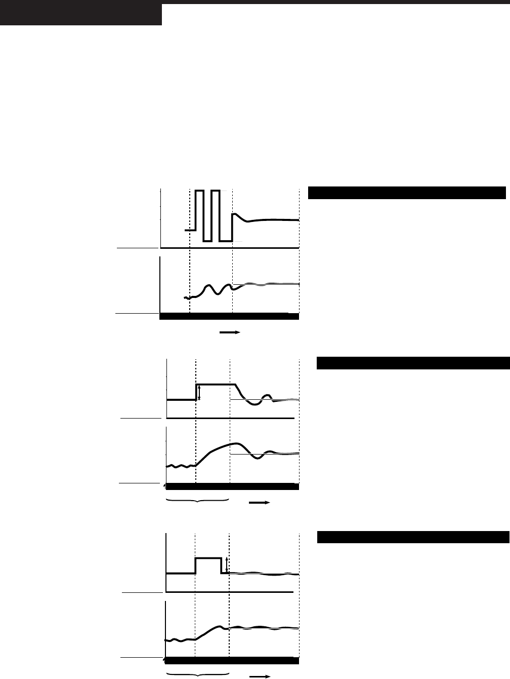
Figure 7.12
Pretune TYPE 1, 2 and
3 with Adaptive Tune
B
A
C
➔
➔
NOISE BUMP
➔
ADAPTIVE
SP
• A to B is a 5 second noise band measurement.
• B to C is an open loop bump test to determine initial PID values
and response time.
• C is Pretune completed, so Adaptive PID control begins if ENABLED.
➔
TIME
TIME
B
A
0%
30%
50%
0%
70%
100%
300
500
700
900
➔
➔
SP
CONTROL
OUTPUT
PV
• A to B is ON/OFF control to determine initial PID values.
• B is Pretune completed, so Adaptive PID control beings if ENABLED.
Note: Noise Band and Resp. Time must be entered before
enabling Adaptive TUne)
TYPE 1 Pretune/Adaptive Control
Out Step
Out Step
B
A
C
➔
➔
NOISE BUMP
➔
ADAPTIVE
SP
• A to B is a 5 second noise band measurement.
• B to C is an impulse to determine initial PID values and response
time.
• C is Pretune completed, so Adaptive PID control begins if ENABLED.
➔
High Out Limit
Low Out Limit
PRETUNE
ADAPTIVE
Pretune
TIME
Pretune
0
0%
30%
50%
0%
70%
100%
300
500
700
900
CONTROL
OUTPUT
PV
TYPE 2 Pretune/Adaptive Control
0
0%
30%
50%
0%
70%
100%
300
500
700
900
CONTROL
OUTPUT
PV
TYPE 3 Pretune/Adaptive Control
0