
User`s manual


Table Of Contents
- 535 User's Manual
- Table of Contents
- Chapter 1: Introduction
- Chapter 2: Basic Interface
- Chapter 3: Installation
- Chapter 4: Hardware Set Up
- Chapter 5: Software Configuration
- Chapter 6: Tuning
- Chapter 7: Applications
- Control Type
- Alarms
- Duplex Control
- Slidewire Position Proportioning Control
- Velocity Position Proportioning Control
- Staged Outputs
- Retransmission
- Digital Inputs
- Remote Setpoint
- Multiple Setpoints
- Multiple Sets of PID Values
- POWERBACK
- Self Tune–POWERTUNE®
- Ramp-To-Setpoint
- Input Linearization
- Load Line
- Security
- Reset Inhibition
- Process Variable Reading Correction
- Serial Communications
- Cascade Control
- Ratio Control
- Appendix 1: Menu Flowcharts
- Appendix 2: Parts List
- Appendix 3: Troubleshooting
- Appendix 4: Calibration
- Appendix 5: Specifications
- Appendix 6: Glossary
- Appendix 7: Isolation Block Diagram
- Return Procedures and Warranty Information
- 500 Series Process Controllers User's Manual
535 User's Manual Chapter 6 65
Tuning
Access Set Up Return to Operation Next menu Next parameter Next value Access Tuning Return to Operation
+
FAST MENU
DISPLAY
+
MENU MENU
▲ ▼
MENU DISPLAYFAST
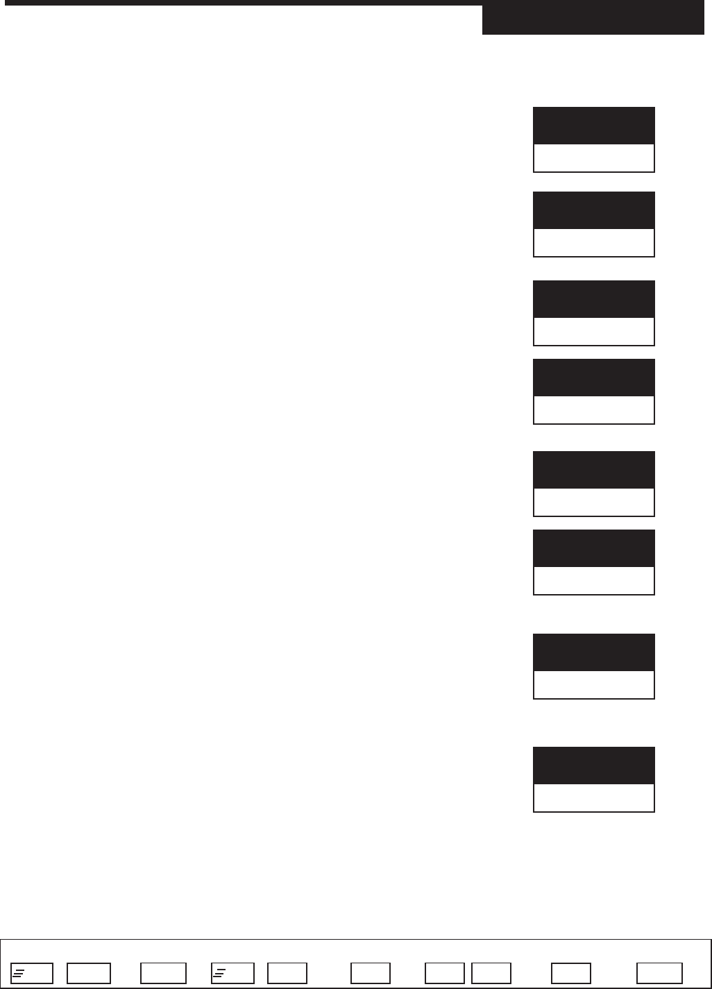
9. DEADBAND:1
Defines the dead band for control output 1 when using on/off control.
R 1 to 99999 in engineering units
D 2
10. P. PROP. D.B.
Defines the dead band setting for a slidewire position proportioning output.
R 0.5 to 10.0%
D 2.0%
11. A. PID OFST.:1
For duplex applications, defines the offset for the first output.
R –50.0% to 50.0%
D 0.0%
11B. ON OFST.:1
For On/Off applications, defines the offset for the first output.
R -9999 to 99999 in engineering units
D 0
12A. PID OFST.:2
For duplex applications, defines the offset for the second output.
R –50.0% to 50.0%
D 0.0%
12B. ON OFST.:2
For On/Off applications, defines the offset for the second output.
R -9999 to 99999 in engineering units
D 0
13. REL. GAIN:2
Defines the adjustment factor for the second output’s proportional band. It is
multiplied by the effective gain of output 1 to obtain the second output's pro-
portional band.
R 0.1 to 10.0
D 1.0
14. CYCLE TM.:2
Defines the cycle time for control output 2 when using a time proportioning
output.
R 0.3 to 120.0 seconds.
D 15.0 seconds
DEADBAND:1
2
REL. GAIN:2
1.0
P.PROP.D.B.
2.0
PID OFST.:1
0
CYCLE TM.:2
15.0
ON/OFST.:1
0
PID OFST.:2
0
ON/OFST.:2
0