
User`s manual


Table Of Contents
- 535 User's Manual
- Table of Contents
- Chapter 1: Introduction
- Chapter 2: Basic Interface
- Chapter 3: Installation
- Chapter 4: Hardware Set Up
- Chapter 5: Software Configuration
- Chapter 6: Tuning
- Chapter 7: Applications
- Control Type
- Alarms
- Duplex Control
- Slidewire Position Proportioning Control
- Velocity Position Proportioning Control
- Staged Outputs
- Retransmission
- Digital Inputs
- Remote Setpoint
- Multiple Setpoints
- Multiple Sets of PID Values
- POWERBACK
- Self Tune–POWERTUNE®
- Ramp-To-Setpoint
- Input Linearization
- Load Line
- Security
- Reset Inhibition
- Process Variable Reading Correction
- Serial Communications
- Cascade Control
- Ratio Control
- Appendix 1: Menu Flowcharts
- Appendix 2: Parts List
- Appendix 3: Troubleshooting
- Appendix 4: Calibration
- Appendix 5: Specifications
- Appendix 6: Glossary
- Appendix 7: Isolation Block Diagram
- Return Procedures and Warranty Information
- 500 Series Process Controllers User's Manual
54 Chapter 5 535 User's Manual
Controller Set Up
PARAMETER VALUE CHARTS
This section of value charts is provided for logging in the actual parameter
values and selections for the process. It is recommended that these pages
be photocopied so there will always be a master.
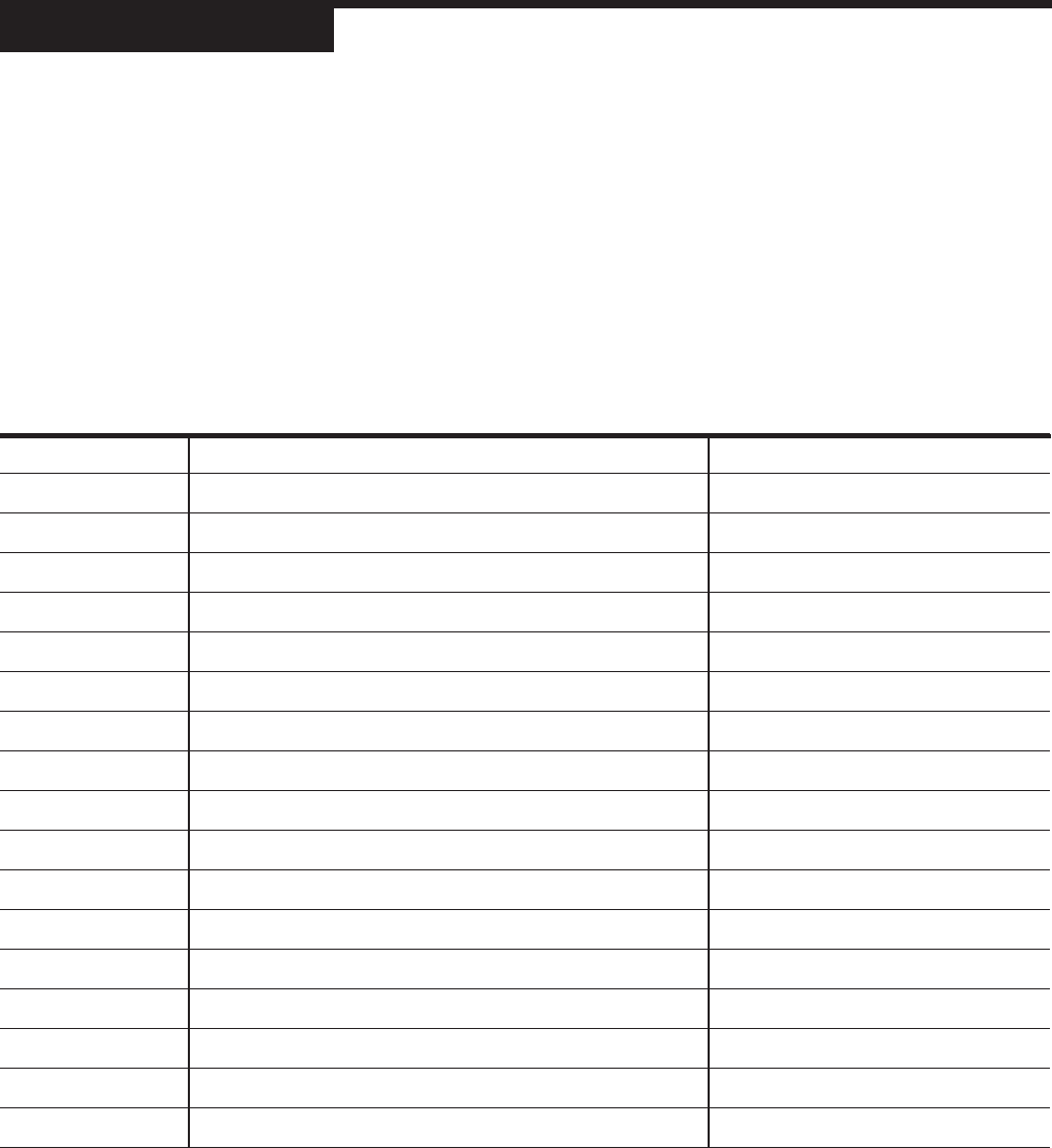
CONFIG
Parameter Description Values
1. CTRL. TYPE Defines fundamental controller Set Up
2 LINE FREQ. Defines the power source frequency
3 PV SOURCE Defines how PV input is derived from PV1 and PV2
4 REM. SETPT. Selects function of the remote setpoint
5 OUTPUT 2 Function of the second output
6 OUTPUT 3 Function of the third output
7 OUTPUT 4 Function of the fourth output
8 ANLG.RNG.:1 Output signal for the first output
9 ANLG.RNG.:2 Output signal for the second output
10 ANLG.RNG.:3 Output signal for the third output
11 ANLG.RNG.:4 Output signal for the fourth output
12 CONTACT 1 Operation of the first digital input
13 CONTACT 2 Operation of the second digital input
14 CONTACT 3 Operation of the third digital input
15 CONTACT 4 Operation of the fourth digital input
16 CONTACT 5 Operation of the fifth digital input
17 LOOP NAME Nine character message associated with control loop