
User`s manual


Table Of Contents
- 535 User's Manual
- Table of Contents
- Chapter 1: Introduction
- Chapter 2: Basic Interface
- Chapter 3: Installation
- Chapter 4: Hardware Set Up
- Chapter 5: Software Configuration
- Chapter 6: Tuning
- Chapter 7: Applications
- Control Type
- Alarms
- Duplex Control
- Slidewire Position Proportioning Control
- Velocity Position Proportioning Control
- Staged Outputs
- Retransmission
- Digital Inputs
- Remote Setpoint
- Multiple Setpoints
- Multiple Sets of PID Values
- POWERBACK
- Self Tune–POWERTUNE®
- Ramp-To-Setpoint
- Input Linearization
- Load Line
- Security
- Reset Inhibition
- Process Variable Reading Correction
- Serial Communications
- Cascade Control
- Ratio Control
- Appendix 1: Menu Flowcharts
- Appendix 2: Parts List
- Appendix 3: Troubleshooting
- Appendix 4: Calibration
- Appendix 5: Specifications
- Appendix 6: Glossary
- Appendix 7: Isolation Block Diagram
- Return Procedures and Warranty Information
- 500 Series Process Controllers User's Manual
535 User's Manual Chapter 5 27
Controller Set Up
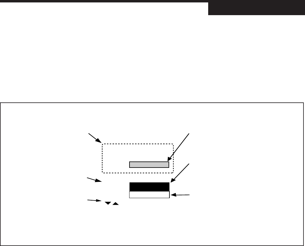
Figure 5.1
Menu Flowchart for Set Up
CONFIG.
MENU
press:
press:
(D)
INDICATOR
MENU/FAST
press:
press MENU/FAST
Go to next Menu Block:
When initially setting up the
controller, cycle through all the
parameters in each Menu.
Press the MENU+FAST to
advance to the next Menu.
Press MENU to advance to the
next parameter (this also sets the
value for the current parameter.
Use arrow keys to select a value).
This is a Menu.
Its name will show in the 2nd display.
This is a menu Parameter.
The name shows in the 3rd display.
In this manual, independent parameters appear
as white text on black, and dependent
parameters appear as black text on white.
Use the arrows keys to enter
numerical values, and/or move
through the selection group.
This is a parameter Value.
These values appear in the 3rd display,
replacing the parameter name.
In this manual, parameter graphics indicate
the default (factory) setting.
If the default value is dependent on other
variables, (D) is shown.
CAUTION!
All software changes occur in real time;
always perform set up functions under
manual operation.
CHAPTER 5
SOFTWARE CONFIGURATION
The software configuration menus of the 535 contain user-selected variables
that define the action of the controller. Read through this section before making
any parameter adjustments to the controller.
MENUS
In Set Up mode, there are 13 sets of options that control different aspects of 535
operation; in Tuning mode, there is one. Each set of options is called a menu.
When traversing the two modes, the menu names appear in the 2nd display.
CONFIG Mode selection and input/output hardware assignments
PV1 INPUT 1st process variable input options
PV2 INPUT 2nd process variable input options
CUST. LINR. Linearization curve options for PV1 input.
CONTROL Control options
ALARMS Alarm options
REM. SETPT. Controller remote setpoint options
RETRANS. Retransmission output options
SELF TUNE Self tune algorithm options
SPECIAL Special feature options
SECURITY Security functions
SER.COMM. Serial Communications options (requires comm. board)
and
TUNING Tuning parameters configuration (see Chapter 6)
NOTE: For information about the
Tuning menu/mode, refer to Chapter 6.
For more information about set up
parameters and 535 applications, refer
to Chapter 7.