
User`s manual


Table Of Contents
- 535 User's Manual
- Table of Contents
- Chapter 1: Introduction
- Chapter 2: Basic Interface
- Chapter 3: Installation
- Chapter 4: Hardware Set Up
- Chapter 5: Software Configuration
- Chapter 6: Tuning
- Chapter 7: Applications
- Control Type
- Alarms
- Duplex Control
- Slidewire Position Proportioning Control
- Velocity Position Proportioning Control
- Staged Outputs
- Retransmission
- Digital Inputs
- Remote Setpoint
- Multiple Setpoints
- Multiple Sets of PID Values
- POWERBACK
- Self Tune–POWERTUNE®
- Ramp-To-Setpoint
- Input Linearization
- Load Line
- Security
- Reset Inhibition
- Process Variable Reading Correction
- Serial Communications
- Cascade Control
- Ratio Control
- Appendix 1: Menu Flowcharts
- Appendix 2: Parts List
- Appendix 3: Troubleshooting
- Appendix 4: Calibration
- Appendix 5: Specifications
- Appendix 6: Glossary
- Appendix 7: Isolation Block Diagram
- Return Procedures and Warranty Information
- 500 Series Process Controllers User's Manual
4 500 Series Installation Guide
Installation
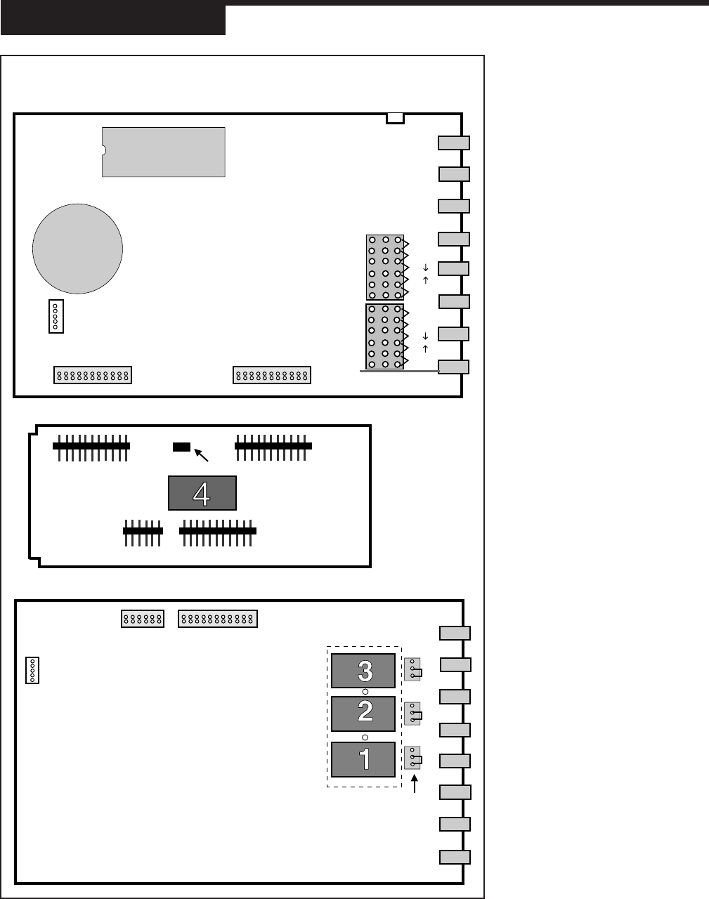
Figure 2
Microntroller Board,
Option Board, and
Power Supply Board
NOTE:
If you replace the EPROM chip, you
must align the notch facing the front
of the unit.
NOTE:
The 5- and 22-Pin connnectors on
the boards are all keyed so they
will only align one correct way.
Front of Unit Back of Unit
(toward Operator Interface) (toward rear terminals)
Male 22-Pin
Connector
Male 22-Pin
Connector
Male 12-Pin
Connector
Male 22-Pin
Connector
Output 4
5-Pin Connector
Female 22-Pin Connector
Female 22-Pin Connector
5-Pin Connector
Module
Retention
Plate
over Outputs 1,2,3
12-Pin Female
Connector
22-Pin Female
Connector
Jumpers
NO and NC
V
MA
V
MA
TC
TC
RTD
NO J1 NC
NO J2 NC
NO J3 NC
TB1
PV1
2ND
TB2
TC
TC
RTD
Remote Setpoint Jumper
EPROM
BATTERY