
User`s manual


Table Of Contents
- 535 User's Manual
- Table of Contents
- Chapter 1: Introduction
- Chapter 2: Basic Interface
- Chapter 3: Installation
- Chapter 4: Hardware Set Up
- Chapter 5: Software Configuration
- Chapter 6: Tuning
- Chapter 7: Applications
- Control Type
- Alarms
- Duplex Control
- Slidewire Position Proportioning Control
- Velocity Position Proportioning Control
- Staged Outputs
- Retransmission
- Digital Inputs
- Remote Setpoint
- Multiple Setpoints
- Multiple Sets of PID Values
- POWERBACK
- Self Tune–POWERTUNE®
- Ramp-To-Setpoint
- Input Linearization
- Load Line
- Security
- Reset Inhibition
- Process Variable Reading Correction
- Serial Communications
- Cascade Control
- Ratio Control
- Appendix 1: Menu Flowcharts
- Appendix 2: Parts List
- Appendix 3: Troubleshooting
- Appendix 4: Calibration
- Appendix 5: Specifications
- Appendix 6: Glossary
- Appendix 7: Isolation Block Diagram
- Return Procedures and Warranty Information
- 500 Series Process Controllers User's Manual
Calibration
A-10 Appendix 4 535 User's Manual
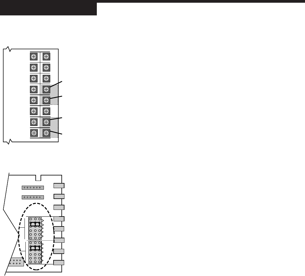
6. Remove both input jumper connectors from the pins in the 2nd position. Place
one of the jumpers on the PV1 position mA pins, and place the other jumper on
the 2nd position mA pins, as shown in Figure A4.7.
7. Reinsert the chassis into the case and apply power. The controller should dis-
play PV1=20mA PRESS ACK to indicate it is ready to calibrate the PV1 milli-
amp input.
8. Connect a precision 20mA input to the PV1 terminals (31 is PV1-, 32 is PV1+).
Make sure the terminal connections are fastened tightly and that a 20mA cur-
rent is flowing through PV1. Do not connect the 20mA current to PV2 yet.
9. Let the controller warm up for at least 10 minutes (keep in normal horizontal
position). Make sure the current is flowing, then press ACK to calibrate the PV1
input.
10. If the controller briefly displays PV2=20mA INPUT, PV1 calibration was suc-
cessful. Move on to step 12.
11. If the controller briefly displays mA CALIB. FAILED, PV1 calibration was not
successful.
Check the 20mA connections, and return to step #3 to recalibrate the PV1 in-
put.
12. Remove the 20mA input from the PV1 terminals, and attach it to the PV2 ter-
minals (see Figure A4.6).
Make sure the terminal connections are fastened tightly and that a 20mA cur-
rent is flowing through PV2.
13. Let the controller warm up for an additional 5 minutes (keep in the normal hori-
zontal position). Make sure the current is flowing, then press ACK to calibrate
the PV2 input.
14. If the controller briefle displays mA CALIB. COMPLETED, PV2 calibration was
successful and the analog milliamp calibration procedure has been completed.
If calibration is complete, power down. Place the jumpers into their original
positions (see Chapter 4).
15. If the controller briefly displays mA CALIB. FAILED, PV2 calibration was not
successful. Check the 20mA connections, and return to step #3 to recalibrate
the PV1 and PV2 inputs.
MILLIAMP OUTPUT CALIBRATION
If the controller uses milliamp outputs, it is usually not necessary to calibrate them.
If the milliamp outputs are being used for accurate retransmission of data, it is rec-
ommended that each output with an analog module be calibrated annually to
maintain optimal performance.
Equipment needed:
• Precision 5-1/2 digit multimeter, e.g., Fluke 8842
®
or HP3478A
®
( 4-1/2 digit
meters sacrifice accuracy)
• Two small pieces of wire for every milliamp output
• Test leads with banana clips
• #2 Phillips screwdriver
1. Disconnect power to the instrument.
2. Remove chassis from case.
V
MA
TCs
RTD
TCt
TB1
PV1
V
MA
2ND
PUT
PER
RATION
TCs
RTD
TCt
TB2
RATION
ERS—
ECT V
TCs
P2
P1
Figure A4.7
Analog mA Input Jumper Positions
23
24
21
22
19
20
17
18
29
30
27
28
25
26
32
31
PV1–
PV1+
PV2–
Wires to 20mA
current (floating)
PV2+
Figure A4.6
Analog mA Input Calibration Wiring