
User`s manual


Table Of Contents
- 535 User's Manual
- Table of Contents
- Chapter 1: Introduction
- Chapter 2: Basic Interface
- Chapter 3: Installation
- Chapter 4: Hardware Set Up
- Chapter 5: Software Configuration
- Chapter 6: Tuning
- Chapter 7: Applications
- Control Type
- Alarms
- Duplex Control
- Slidewire Position Proportioning Control
- Velocity Position Proportioning Control
- Staged Outputs
- Retransmission
- Digital Inputs
- Remote Setpoint
- Multiple Setpoints
- Multiple Sets of PID Values
- POWERBACK
- Self Tune–POWERTUNE®
- Ramp-To-Setpoint
- Input Linearization
- Load Line
- Security
- Reset Inhibition
- Process Variable Reading Correction
- Serial Communications
- Cascade Control
- Ratio Control
- Appendix 1: Menu Flowcharts
- Appendix 2: Parts List
- Appendix 3: Troubleshooting
- Appendix 4: Calibration
- Appendix 5: Specifications
- Appendix 6: Glossary
- Appendix 7: Isolation Block Diagram
- Return Procedures and Warranty Information
- 500 Series Process Controllers User's Manual
Operation
535 User's Manual Chapter 2, Controller Operation 5
CHAPTER 2
BASIC INTERFACE
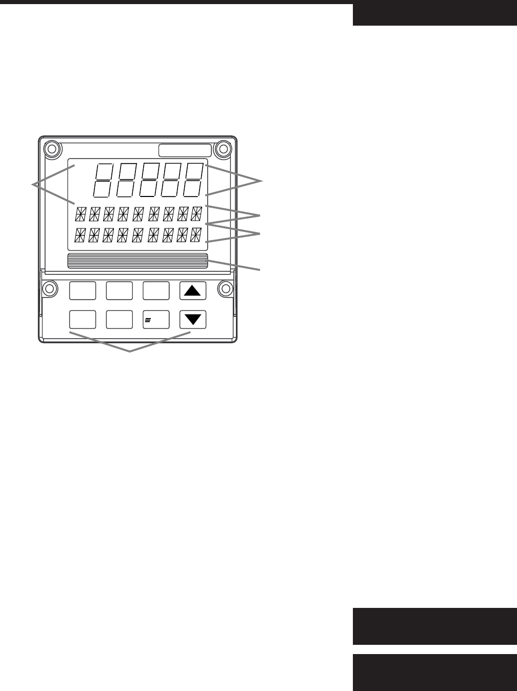
DISPLAYS
The display strategy of the 535 Process Controller is the same for all control
modes.
1st Display (five 7-segment digits)
• For the process variable value.
2nd Display (nine 14-segment digits)
• For the setpoint, deviation, output level or valve position (if available)
• In TUNING or SET UP mode, for the parameter name.
• Upon power up, indicates the current setpoint.
3rd Display (nine 14-segment digits)
• For alarm messages, loop name, errors, etc.
• In TUNING or SET UP mode, the value or choice of parameter shown in
the 2nd display.
ICONS (LIT)
OUT Indicates either 1) relay output is energized; or 2) analog output is
greater than 0%.
ALM1 Indicates the respective alarm (one) is active.
ALM2 Indicates the respective alarm (two) is active.
Figure 2.1
Operator Interface
OUT OUT OUT
1212
535
MANUAL DISPLAY SET PT
ACK MENU FAST
OUT
1 2
ALM
1 2
Icons
1st
Keys
2nd
3rd
Location for
identification
label
Displays:
ALM ALM ALM
1212