
User`s manual


Table Of Contents
- 535 User's Manual
- Table of Contents
- Chapter 1: Introduction
- Chapter 2: Basic Interface
- Chapter 3: Installation
- Chapter 4: Hardware Set Up
- Chapter 5: Software Configuration
- Chapter 6: Tuning
- Chapter 7: Applications
- Control Type
- Alarms
- Duplex Control
- Slidewire Position Proportioning Control
- Velocity Position Proportioning Control
- Staged Outputs
- Retransmission
- Digital Inputs
- Remote Setpoint
- Multiple Setpoints
- Multiple Sets of PID Values
- POWERBACK
- Self Tune–POWERTUNE®
- Ramp-To-Setpoint
- Input Linearization
- Load Line
- Security
- Reset Inhibition
- Process Variable Reading Correction
- Serial Communications
- Cascade Control
- Ratio Control
- Appendix 1: Menu Flowcharts
- Appendix 2: Parts List
- Appendix 3: Troubleshooting
- Appendix 4: Calibration
- Appendix 5: Specifications
- Appendix 6: Glossary
- Appendix 7: Isolation Block Diagram
- Return Procedures and Warranty Information
- 500 Series Process Controllers User's Manual
535 User's Manual Chapter 7 103
Applications
V. RATIO CONTROL
Ratio Control is employed in mixing applications that require the materials to
be mixed to a desired ratio.
For example: A given process requires Material A to be blended with Material
B in a 2:1 ratio. Material B is uncontrolled or wild. Flow sensors/transmitters
are used to measure the flow rate of each stream. The flow signal for Material
A is wired to the process variable input, and the flow signal for Material B is
wired to the remote setpoint input of the 535.
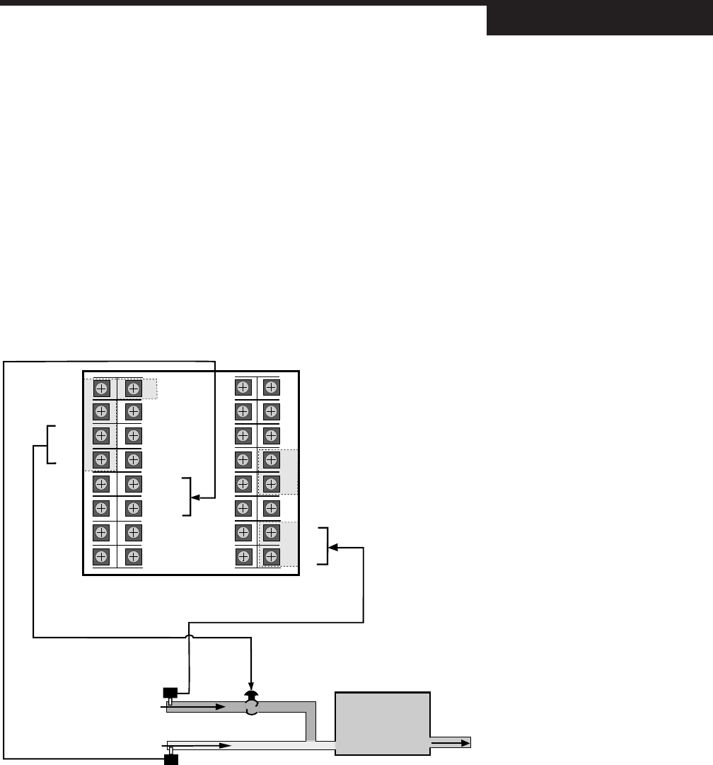
For this example, as shown in Figure 7.21, we would set RSP RATIO to 2.0. If
the flow of Material B is measured at 50 gallons/minute, the effective remote
setpoint value would be 2 times 50, or 100. The 535 controller would try to
maintain the flow of Material A at 100. As the flow of Material B changes, the
setpoint would change accordingly, always in a 2:1 ratio.
Hardware Configuration
• Set the process variable jumper and remote setpoint jumper to mA. Make
sure that both inputs are set up to accept the corresponding signal from the
flow transmitters.
• Wire as in Figure 7.21.
Software Configuration
1. Make sure that the range of both inputs matches the range of the
corresponding transmitter:
1
2
3
4
5
6
7
816
15
14
13
12
11
10
9
17
18
19
20
21
22
23
24
32
31
30
29
28
27
26
25
BOTTOM
(As viewed from rear)
EARTH GND
PV 1+
PV 1–
AC+
AC–
OUT 1–
OUT 1+
MIXER
CONTROLLED STREAM
RSP+
RSP–
flow
sensor
WILD STREAM
MATERIAL B
MATERIAL A
flow
sensor
Figure 7.21
Ratio Control in Mixing Applicatoin