co c c: ~ 1../.1 i=l m i=»PlOFESSION AI SEPliES Remote Start Installation Guide for models: ca4054 ca4554 2014 Voxx Electronics Corporation. All rights reserved.
Before You Begin ......................................................................................... 3 Wire Connection Guide ............................................................................... 4 4 Pin Main Harness ................................................................................... 5 3 Pin Parking Light Harness ...................................................................... 6 6 Pin Start Harness .........................................................................
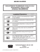
BEFORE YOU BEGIN FOR AUTOMATIC TRANSMISSION VEHICLES ONLY. PROFESSIONA L INSTALLATION STRONGLY RECOMMENDE D Roll down window to avoid locking keys in vehicle during installation Avoid mounting components or routing wires near hot surfaces Avoid mounting components or routing wires near moving parts Tape or loom wires under hood for protection and appearance Use a Digital Multi Meter for testing and verifying circuits.
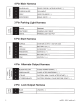
Pin Main Harness BLUE/BLACK START STATUS I ACTIVE OUTPUT ( - ) PURPLE/WHITE TACH INPUT GRAY HOOD PIN INPUT (-) BROWN/RED BRAKE INPUT ( + ) 3 Pin Parking Light Harness (f) Zl-I a..
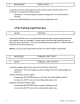
4 Pin Main Harness 1 BLUE/BLACK START STATUS I ACTIVE OUTPUT ( - ) This wire provides a ground output when the remote start function is activated and remains until 4 seconds after the remote start is shutdown. If this wire will be used for multiple application's a 1 amp diode is required in-line with the stripe facing the control module. 2 PURPLE/WHITE TACH INPUT Locate the vehicle's ignition coil or fuel injector in the engine compartment. Verification: Test using the following procedure: 1. 2. 3.
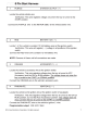
4 BROWN/RED BRAKE INPUT ( + ) Locate the vehicle's brake light wire at the brake pedal mounted switch. This connection is required for Remote Start. Verification: This wire registers positive voltage when the brake pedal is pressed. Connect the BROWN/RED wire to the vehicle's brake light wire. 3 Pin Parking Light Harness 1 BLACK GROUND Connect the BLACK wire to a solid chassis ground point using a ring terminal and self tapping screw (not supplied).
6 Pin Start Harness 1 PURPLE STARTER OUTPUT ( + ) Locate the vehicle starter wire. Verification: This wire registers voltage only when the key is turned to the START position. Connect the PURPLE wire to the MOTOR SIDE of the vehicle starter wire. 2 RED BATTERY 12V ( +) Locate 1 of the vehicle's constant 12 Volt battery wires at the ignition switch. Verification: This wire will register ( + ) voltage in all positions of the ignition switch. Connect the RED wire to the constant 12 Volt battery wire.
5 RED/WHITE BATTERY 12V ( +) Locate 1 of the vehicle's constant 12 Volt battery wires at the ignition switch. Verification: This wire will register ( + ) voltage in all positions of the ignition switch. Connect the RED/WHITE wire to the constant 12 Volt battery wire. NOTE: Remove all fuses until all connections are made. 6 PINK IGNITION 1 ( +) Locate the vehicle's ignition wire at the ignition switch. Verification: This wire registers voltage when the key is turned to the ON (or RUN) position.
3 GREEN/WHITE PULSE AFTER SHUTDOWN ( - ) This wire will supply a (-) 200mA pulse after the remote start shuts down. This is typically used to re-lock the vehicle's doors if they unlock upon remote start shutdown. It can also be used to pulse a door pin-switch wire to prevent the vehicle's accessories from remaining on after remote start shutdown. This output is configurable in option programming.
Additional Ports Antenna I LED I Programming Port Mount the supplied antenna/receiver to a clear spot on the vehicle's windshield that will not block the driver's vision. A good location is usually high on the windshield near the rear view mirror. Be careful not to mount the antenna/receiver on any metallic window film, as this will effect system range. Route the antenna/receiver cable to the control module and plug into the antenna port.
Set Up & Programming Transmitter Programming - Feature Bank 1 1. Turn the ignition ON. 2. Press and hold the valet/override button. 3. Within 10 seconds the parking lights will flash (3) three times. 4. Press 1 button of each transmitter you wish to program. 5. The system will respond with 1 light flash for each accepted transmitter. 6. Pressing the override button at anytime during programming will advance to the next bank.
Feature Bank 1 - 3 Flashes Transmitter Programming Refer to transmitter programming. Feature Bank 2 - 4 Flashes Feature Bank 3- 5 Flashes Factory Disarm Lt Green I Black 1 LED Flash 4 LED Flash 1 LED Flash Factory Disarm NIA Factory Disarm Factory Disarm Factory Disarm 500mS 350mS I Start Status 2 NOTE: On this model the Lt Green I Black Output wire can be configured in Bank 3 or Bank 5. Any changes to this feature in Bank 5 will override changes made in Bank 3.
Feature Bank 4- 6 Flashes Feature Bank 5 - 7 Chirps 4 Pin Alternate Output Control NOTE: On this model the Lt Green I Black Output wire can be configured in Bank 3 or Bank 5. Any changes to this feature in Bank 5 will override changes made in Bank 3. 4 Black I Yellow Output Pulse During Crank Ground While Running Ignition Accessory Ground While Running Ignition Accessory 2014 Voxx Electronics Corporation. All rights reserved.
Tach Programming The unit will not operate unless tach is programmed or tach less option is turned ON. If an attempt is made to start the vehicle via the remote start without first programming tach, the unit will flash the parking lights 7 times indicating tach has not been learned and stored. If the tach rate is not properly programmed to the specific vehicle, the unit may not realize that the vehicle is running in certain instances and reengage the starter motor.
Feature Descriptions Feature Bank 2- Security 1 - 8 Not Available. 9- OBI Port Protocol: Determines the protocol type in which the OBI port uses to interface with external modules. OBI Protocol ADS Protocol Feature Bank 3 - Output Control 1 -Extended Lock Pulse: Controls the timing of the BLUE unlock output wire. 1 Second - Single 1 second unlock pulse. 3.5 Seconds - Single 3.5 second unlock pulse. Double Pulse Unlock - Double 1 second unlock pulse.
Feature Bank 4 - Remote Start Control 1 - Not Available. 2 - Run Time: Controls the time in minutes that the vehicle will stay running under control of the remote start until the system times out. The system may also be shut down at any time by use of the transmitter or system shutdowns. 3- Running Lights: Controls the WHITE parking light output wire during remote start. Steady - Parking lights constant during the remote start cycle.
7 - Crank Average I Crank Time: The length of time in which the remote start will crank the vehicle's starter. Crank Average - Determines crank time by averaging the last 8 times the vehicle was started with the key. Preset Time - Preset starter output time. (see crank time) 8 - Gas I Diesel: Selects engine type and delay time for the starter output wire during remote start activation. Gas- Gasoline engine, no delay for the starter output wire.
Feature Bank 5 - 4 Pin Alternate Output Control 1 - Lt Green/Black Output : Controls the LT GREEN/BLACK output activation type and timing. Pulse before Start I During Unlock - 1 second pulse when remote start is activated. Also a 1 second pulse when unlock is pressed. Ground While Running - Continuous output for the entire remote start sequence until after the vehicle shuts down. Ignition - Output becomes active with the same timing as the ignition output and does not drop out during crank.
4 - Black/Yellow Output : Controls the BLACK/YELLOW output activation type and timing. Pulse During Crank - Output becomes active with the same timing as the starter output wire, during crank only. Ground While Running - Continuous output for the entire remote start sequence until after the vehicle shuts down. Ignition - Output becomes active with the same timing as the ignition output and does not drop out during crank.
2 Way Transmitter Notifications- CA4554 ONLY FUNCTION BEEPS I LED FLASHES Activation 1 Beep I Flash Confirm Remote Start 4 Beeps I Flashes (repeats 3 times) Remote Start Running 1 Flash per second for duration run time Remote Start Shutdown 3 Long Beeps I Flashes (repeats 3 times) Low Battery 2 Beeps I Flashes when button is pressed Remote Start Shutdown Diagnostics If the remote start shuts down or fails to start, the parking lights will flash one of the patterns below indicating the shutdown i
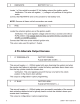
N 0 ....... #4120104 ~ ~ X BLUE OPEN UNLOCK (-) BLACK/YELLOW GREEN/WHITE LT BLUE LT GREEN/BLACK PULSE DURING CRANK (-) PULSE AFTER SHUTDOWN ( - ) FACTORY ARM I PULSE AFTER START (-) FACTORY DISARM I PULSE BEFORE START ( - ) X m ro n. a # 4120102 ::l ;::;· (/J 0 0...., '0 0 ...., D ~ 6' ::l #4120103 ~ ...., (Q' ~ Ui co (/J CD < CD a.
ca4054- 4554 Install rev A
2014 Voxx Electronics Corporation. All rights reserved.
Voxx Electronics Corporation. Customer Service 1-800-421-3209 WWW.CODE-ALARM.COM FCC COMPLIANCE This device complies with Part 15 of the FCC rules and with RSS-21 0 of Industry Canada. Operation is subject to the following two conditions: 1. This device may not cause harmful interference, and 2. This device must accept any interference received, including any interference that may cause undesired operation.
CCJCc:~IA~m Remote Start System IMPORTANT NOTE: The operation of the Security and Convenience System as described in this manual is applicable to most vehicles. However, due to the configuration of some vehicles, some functions AND/OR SAFETY PRECAUTIONS may not apply. Please see your installing dealer for more information. 2014 Voxx Electronics Corporation. All rights reserved.
Using Your Remote Vehicle Starter Remote Starting Your Vehicle The system WILL NOT start the vehicle if any one of the following 1. The vehicle's hood is opened. 2. The gear shift selector is not in Park. 3. The brake pedal is depressed. 4. Valet Mode is active. situations exist: 1. To start the vehicle, press and release the 0 button 2 times within 2 seconds. The vehicle will start and remain running for the pre-programmed 5, 10, 15, 20, 45 or 60 minute run cycle.
Operating the 2 I 3 Hour Start Up Timer Mode The system has the ability to start the vehicle every 2 or 3 hours for a 48 hour period. This feature is especially useful in cold climates where the only means to keep the engine and engine fluids warm is to periodically start the engine. The default setting is 3 hour, selection between 2 or 3 hour is made in option programming. WARNING! Be certain that the vehicle is outdoors before using this or any remote starting device.
Valet Mode Valet Mode is used to disable the system from remote starting. To enter or exit valet mode simply follow the 4 steps outlined below: 1. Turn the vehicle's ignition ON. 2. Push and hold the programming/valet button. 3. The LED will turn on solid when valet mode is active 4. Release the programming/valet button.
Replacing Remote Control Batteries 1 Way Remote Control, CATX1 B: The batteries (model CR2016) inside each remote control should last approximately 1 year under normal use. When the batteries become weak you will notice the remote control range (the distance from the vehicle the remote control will work) deteriorate and the small LED on the remote control will dim. To replace the remote control batteries: 1. Unsnap and disassemble the halves of the remote control. 2.
Code Systems, Inc. Limited Lifetime Warranty Code Systems Inc.
This product is covered by one or mote of the following U.S. Patents; Other Patents pending. 0407,034,0580,160,5,132.660. 51157.375~ 5.193,141. 5.245.694. 5.315.285. 5.334.969 5,349,931~ 5.,357.560, 5.381.128•.5,412.371. 5,467.070. 5.469.141, 5.469~151. 5~506.568 51532.670. 5.534.845. 5.563,576, 5~583.600. 5.572.185. 5.602.535, 5.614,883. 5t617.819 5,646.591' 5~650,774. 5,656*868, 5,673.017, 5t656,997.• 5,712,638, 5,783.988, 5t783,989 5.798,711. 5.805.056. 5.8191588* 5,8.28,316. 5.838.255. 5.850.173.
Voxx Electronics Corporation. Customer Service 1-800-421-3209 WWW.CODE-ALARM.COM FCC COMPLIANCE This device complies with Part 15 of the FCC rules and with RSS-21 0 of Industry Canada. Operation is subject to the following two conditions: 1. This device may not cause harmful interference, and 2. This device must accept any interference received, including any interference that may cause undesired operation.
WARNING THIS VEHICLE IS EQUIPPED WITH A REMOTE CONTROLL ED CAR STARTER BEFORE SERVICING THIS VEHICLE, REMOVE THE MAIN POWER FUSE (RED WIRE) TO THE CAR STARTER OR DISCONNE CT THE VEHICLE BATTERY.