Comfoair 140 Manual
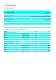
TABLE OF CONTENTS 1. 1.1 2. 2.1 2.2 2.3 3. FOREWORD.................................................................................... 3 GENERAL ....................................................................................................... 3 SAFETY........................................................................................... 3 GENERAL SAFETY REGULATIONS .................................................................... 3 SAFETY PRECAUTIONS, SAFETY MEASURES ......................
1. FOREWORD This operating and installation manual contains installation and operating instructions for the COMFOAIR 140 heat recovery unit. The warranty will be voided if: • The unit is operated without filter, • Proper filter maintenance is not carried out, • Original spare parts were not used, or unauthorised modifications were made to the unit. READ THIS MANUAL CAREFULLY BEFORE PUTTING THE UNIT INTO OPERATION. 1.
2.2 • • 2.3 Safety Precautions, Safety Measures It must not be possible to touch the fan wheels with your hand. The unit may therefore only be operated with the duct system connected. The unit cannot be opened without the use of tools. In conjunction with possible later warranty claims and in order to ensure the proper function of your system, we recommend that you conclude a service contract with an approved specialist company.
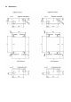
3. TECHNICAL DATA 3.1 Specification 3.1.1 Technical Data COMFOAIR 140 Heat exchanger efficiency approx. 92% Fans Constant volumetric flow with parallel flow technology Voltage 230 V~, 50 Hz Dimensions H x W X D 740 x 595 x 260 mm Connection fittings 4x DN 125 mm Weight approx. 28 kg Installation position Wall or ceiling installation Heat efficiency level The standard unit is delivered as a right-hand version.
3.
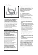
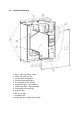
3.3 Circuit Diagram * *Important installation instruction If a geothermal heat exchanger is not provided, we recommend the installation of a preheater unit for the outside air. This prevents icing of the heat exchanger at extreme ambient temperatures. 4. SYSTEM 4.1 Figure 1 The COMFOAIR 140 is equipped with an anti-freeze system without additional auxiliary energy.
4.2 Transport and Packaging Take the necessary care and attention when transporting and unpacking the unit. Damage to the packaging must be recorded on the delivery note on receipt of the goods. Dispose of the packaging materials in an environmentally safe manner. 4.
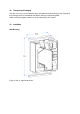
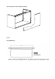
Cover element for wall installation (option) Figure 3 Ceiling Mounting
4.
4.5 Electrical Connection The casing of the COMFOAIR 140 is provided with a cable opening. The electrical connection is made at the terminal box inside the housing. The terminals are numbered. Observe the conductor designations. Incorrect connection of the cables will result in damage to the electronics. The bathroom switch must be connected as an off-circuit two-way switch or button.
5. COMMISSIONING 5.1 Operating Panel Displays: "1" "2" "3" " xx " "." Ventilation “Level 1” Ventilation “Level 2” Ventilation “Level 3” Malfunction code Bypass open Menu This button is used to activate and deactivate the menu. OK This button is used to confirm set values / parameters and menu points. When cleaning the filters it is used as a reset button. When the air intake fan is in operation, the green LED “Air intake” lights up.
Menu structure The following programmes can be selected using the buttons MENU, , and OK: Display Operating mode User access Service access P1 No function - - P2 Forced ventilation times Yes Yes P3 Set fan speeds No Yes P4 Set temperatures No Yes P5 Display and change status No Yes P6 Display malfunctions No Yes P7 Reset No Yes Access to the menus P3 to P7 is possible only after entering the code 352. Changes to the values are made at your own risk.
5.2 Programming Example Set the speed level “2” (normal ventilation) of the air intake fan to 40. Number 1 2 3 4 5 6 7 8 9 10 11 12 13 14 15 16 5.3 Button Display Description Menu ▲ ▲ ▲ OK ▲ OK ▼ OK OK ▲ OK ▼ OK MENU MENU P1 P2 " 1 -- -- " " ? -- -- " " -- ? -- " " -- ? -- " " -- -- ?.
Number Meaning Min Max Default Unit 36 Intake air fan Level 3 17 100 90 % 37 Current level of exhaust air fan current value % 38 Current level of intake air fan current value % P4 Temperatures Number Meaning Min Max Default Unit 41 42 Comfort temperature 28 40 18 18 °C Post-heater enable temperature 15 5 43 GHE starting temperature low 0 15 7 °C 44 GHE starting temperature high 10 35 23 °C 45 Current value of T1 (outside air) current value °C 46 Current valu
P7 Reset Number Meaning 0 1 Default 71 Acknowledge alarm / malfunction status No acknowledg ement Acknowle dgement 0 72 General acknowledgement: all default values are automatically reset No acknowledg ement Acknowle dgement 0 With Reset P72, “P54” is set to “0”. This must therefore be set to “1” again. For reading out malfunctions, see section 10.
6. SETTING Characteristic Diagram Speed 20% Qv (m³/h) 65 30% 75 40% 85 50% 95 60% 110 70% 125 80% 140 90% 155 100% 170 Diagram 7.1 Constant volumetric flow fans: The Comfoair 140 is equipped with parallel-flow fans with the latest constant volumetric flow technology. This means that a precisely defined volume of air corresponds to every percentage setting (see table above). Intermediate values have to be interpolated. 1. 2. 3. 4. 5. 6. Close all doors and windows.
7. MAINTENANCE / CARE 7.1 General Maintenance of the unit for the end user is limited to the periodic cleaning of the filters and the intake / exhaust air valves and grilles. Twice a year, the texts “FIL” followed by “tEr” appear alternately on the display as a reminder to clean the filters. Cleaning of the valves / grilles is recommended at the same time as the cleaning of the filters. The system must not be operated without filters.
8. MALFUNCTIONS 8.
Fault/malfunction Symptom Display Check No or insufficient Fan not running exhaust air; bathroom or shower remains damp for too long Fan running E1 E1 Loud noise E1/E2 Fan defective Fan pcb defective Control pcb defective Filter clogged Valves/grilles clogged Heat exchanger clogged Fan soiled Ducts clogged Impeller binding or is broken Bearings defective Fan running too fast.
8.2 Bypass Inspection Instructions If 230 V AC is measured between DO3H and N, the flap must open / be open. If 230 V AC is measured between DO4H and N, the flap must close / be closed. Check the connection between pcb and bypass. Air intake and air exhaust fan Check the fans for soiling or mechanical damage. If the fault E1 and/or E2 is displayed, check the wiring. If the wiring is OK, then the fan is defective. The supply voltage to the fans is 230 V.
10. ANNEXES 10.
10.2 EC Declaration of Conformity J.E. Stork Ventilatoren B.V. Lingenstraat 2 8028 PM Zwolle-NL Tel.: 038-4296911 Fax: 038-4225694 Handelsregister Zwolle 22293 EC - declaration of conformity Description : Heat recovery unit type: G90-140 Conforms the following directives : - Machine directive (98/37/EG) - Low voltage directive (73/23/EEC) - EMC directive (89/336/EEC, 92/31/EEC and 93/68/EEC) Zwolle, 22 november J.E. Stork Ventilatoren B.V.
Switzerland Zehnder Comfosystems AG Industriestraße 11 CH-8820 Wädenswil Phone: +41 043 833 2020 Fax: +41 043 833 2021 e-mail: info@comfosystems.com © zehnder comfosystems 849050528engels-1107 Germany Zehnder GmbH Comfosystems Almweg 34 D-77933 LAHR Phone: +49 07821 586 159 Fax: +49 07821 586 302 www.zehnder-online.