
System information


ATS 2000/3000/4000/4500 Programming manual 145
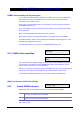
DVMRe Alarm Input Map
Alarm Input:
“*”- Next, DVMRe Alarm Input 1 No relay
Relay:
YES – Enable DVMRe Interface
* - Change 0 - Skip
53. DVMRE ALARM INPUT MAP
DVMRe Alarm Handling via the printer port
In a conventional alarm-handling configuration the alarm devices are connected via the
alarm PCB on the back of the DVMRe unit. Each alarm input corresponds with the
camera input of the same function.
Alarm input to camera assignments can be changed on 10 and 16-channel models via
the DVMRe programming.
On an input trigger, the internal buzzer will be activated and an on-screen alarm display
will be activated.
Macros can be programmed to achieve full CCTV scenarios.
Many different options are possible depending on the programming of the DVMRe.
An additional feature, which can be combined with external an alarm triggering, is a text
insertion to the triggered alarm frame.
The ATS printer interface connection to the DVMRe provides all in one.
53.1. DVMRe Alarm Input Map
This menu controls the setting to trigger an alarm input from the DVMRe by programming
an output of the ATS panel. In total 16 DVMRe Alarm inputs can be linked to an ATS
output. All 255 ATS outputs can be programmed.
Setting or un-setting an ATS output triggers a DVMRe alarm input. ATS outputs are used
rather than event flags because outputs can be activated via time zones as well.
The DVMRe can be programmed to execute a macro linked to a DVMRe input.
High Level Interface (HLI) Control Flags
53.2. Enable DVMRe Interface
Enables the High Level Integration between the ATS panel and the DVMRe.
YES The ATS panel and DVMRe connection can be established and the next
following control flags will be considered.
NO Overrides all other control flags and there will be no communication at all
between the ATS panel and the DVMRe.
Note: If the DVMRe HLI is used, the ATS panel will no longer be able to communicate
with a serial printer.