
Programming instructions

6
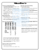
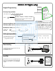
Terminals (Standard Models Only)
1 & 2 (Operation without Batteries) - Optional 7.5 VDC
Voltage for operation without batteries.
3 & 4 (Remote Input) - Wire a Normally Open Contact to
Terminals 3 & 4. Momentarily close to allow person to pass
through door. NOTE: Remote Input is enabled from the
factory.
5 & 6 (Normally Open Relay) - See Function 67 for
programming options for the Relay.
PC Interface - Connect to Serial Port on Computer using
A-PCI interface cable.
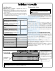
Battery Replacement
When a valid code is entered and the batteries are weak the
lock LED will light amber, and the sounder will sound for 4
seconds. The DL3000 uses 5 AA-size 1.5 volt alkaline
batteries. The lock will function with weak batteries; however
be sure to replace the batteries as soon as possible.
Remove the screw at the bottom of the housing and remove
the cover. Replace all 5 batteries quickly - within 2 minutes.
Note: Do not press any buttons while replacing the batteries
(unless lock programming is to be erased). Pressing any
key will remove the voltage that is required to keep the
system clock and Audit Trail.
Power-Up - Retain Lock Programming
(Audit Trail and Clock Settings lost)
1. Remove at least one battery.
2. Press any key to insure the locks capacitor is fully
Power-Up - Erase All Programming
(Factory Default will be loaded)
1. Remove at least one battery.
2. Press any key to insure locks capacitor is fully discharged.
3. Re-install battery (lock will give 3 short beeps).
4. Press any key within 5 sec after hearing the 3 beeps.
5. A series of 12 slow beeps will be heard followed by 20
seconds of silence, followed by 6 fast beeps.
All programming has been erased and the lock is now ready
for use.
Note: All lock programming can also be erased by entering
Function 99.
Self Diagnostic Indications
Various system tests are performed at power up and during
operation of the lock.
Steady 4 Second Sounder with a Yellow LED indication
every time a user code is entered - indicates a Low
Battery Condition.
Continuous Series of Beeps - indicates the lock detected
a system fault which would not allow any part of the system
to operate. Ensure batteries are good.
Sequence of 7 Beeps Repeated 4 Times with a Yellow
LED indication, every time a user code is entered -
indicates a non-fatal memory or clock error has been
detected. Under this condition, unexpected operation is
possible. Do not mistake the low battery indication as a
memory or clock error.
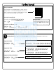
Wire Leads for DL3000WP Models