Trilogy Series DL3000 Programming Instructions ALARM LOCK PLUG IN THEN ENTER YOUR CODE ALARM LOCK DL3000 Trilogy Series Standalone Access Control System ALARM LOCK OI224C 8/98 1
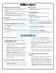
Features -----------------------------------------------------------------------------------------------------4 Audit Trail -------------------------------------------------------------------------------------------------4 User Features -------------------------------------------------------------------------------------------4 150 Scheduled Events --------------------------------------------------------------------------------4 Keypad and Download Programming -----------------------------------------------
Programming Functions ----------------------------------------------------------------------------11 New Master Code---------------------------------------------------------------------------------------11 Add/Delete/Change User Codes --------------------------------------------------------------------11 Disable User----------------------------------------------------------------------------------------------11 Enable User -------------------------------------------------------------------------------------
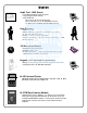
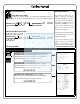
------- AUDIT LOG ------04/07/98 13:06:35 Tue 13:01:59 001 PROGRAM 56 13:01:29 001 PROGRAM 57 13:00:53 001 ENTRY 13:00:26 013 ENTRY 13:00:03 012 ENTRY 12:56:27 001 PROGRAM 2 12:56:27 001 PROGRAM 40 12:56:04 001 PROGRAM 39 12:55:00 NEW CLCK TIME 12:01:39 OLD CLCK TIME 12:00:45 RAM TEST:PASS 12:00:45 POWER UP ------------------------End of Audit Log Audit Trail - 1600 Events • Time/Date Stamped Log of all Entries • Logs program mode changes • View Audit Trail: Print using the AL-IR1 hand-held printer Upload
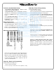
Ambush Function Relay Terminals 1. Connect terminals 5 & 6 to a device able to properly monitor normally open dry contacts for an ambush condition. 2. Program the Relay for Ambush Function Activated (10) using Program Function 67. 3. Set the Ambush Code using Program Function 66. 4. When the ambush code is entered followed by a valid user code, the relay will close for 2 seconds. Ambush Code The ambush code defaults to 99.
Terminals (Standard Models Only) 1 & 2 (Operation without Batteries) - Optional 7.5 VDC Voltage for operation without batteries. 3 & 4 (Remote Input) - Wire a Normally Open Contact to Terminals 3 & 4. Momentarily close to allow person to pass through door. NOTE: Remote Input is enabled from the factory. 5 & 6 (Normally Open Relay) - See Function 67 for programming options for the Relay. PC Interface - Connect to Serial Port on Computer using A-PCI interface cable.
Lock Operation Programming - Notes Important: Before attempting to program any codes or functions, Note the following: • While the lever or knob may be rotated at any time, the latch will not be engaged to unlock the door unless a valid code has been entered. • When a valid code is entered, the lock will unlock immediately and remain unlocked for about 5 seconds (or longer, if reprogrammed by functions 52 and 53). LED Indications Key Press - The red LED will light momentarily whenever a key is pressed.
Battery Installation Remove the back cover and install batteries as shown. The lock will beep 3 times. To load the default program press any key within 5 seconds, the lock will beep slowly while the default values are loaded and beep rapidly upon completion. Entering Program Mode 1. Enter Master Code 1 2 3 4 5 6 Program Mode The keypad sounder will beep every 6 seconds and the keypad LED will flash green every 6 seconds while in program mode when no keys are pressed.
User Programming User code conflicts Add a Basic User Code Care should be taken not to program a new user code which matches the first digits of any other user code. (only the code with the least number of digits would be recognized). Example: If user codes 123 and 123456 are both entered in the system only code 123 would be recognized. Program a User Code of 987. Use Function 2, and add the new user as User 12 (Users 12-50 are Basic Users). Refer to Function 2 (page 11).
Tri-Color Keypad Programming Infrared LED Entering Program Mode PC Interface/AL-DTM 1. Enter Master Code 1 2 3 4 5 6 Default Master Code 2. Enter “BeepBeep” “BeepBeep” ; “BeepBeep” “BeepBeep” Sounder will sound 2 short beeps 4 times to indicate the program mode is active. Program Mode The keypad sounder will beep every 6 seconds and the keypad LED will flash green every 6 seconds while in program mode when no keys are pressed.
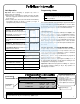
USERS 1. New Master Code (User Number 1) ;1 ;[______] • Master Code must be 6 digits-only. NOTE: Following a power up, Function 1 (New Master Code), must be accessed before any other programming function is permitted. 2. Add/Delete/Change User Codes 2-300 ;2 ;[______]: M ;[___] ;[______]: • User Number must be between 2 and 300.
USERS ;5 5. User Enable with Timeout ;[___] ;[___]: (User Number) (Enter Timeout, XXX Hours) • User Numbers must be between 2-300. • Hours must be between 1 - 999 (XXX Hours) 2 User Lockout Mode Enables/Disables all User Codes (Except User 1 Code) from operating the lock. Note: No other programming functions or schedules will re-enable users. Users must be re-enabled with function 7. 6. Enable Total User Lockout ;6: 7. Disable Total User Lockout ;7: 8.
CLEAR FUNCTIONS 12. Clear All Schedules and Timeout ;12 ;000: Clears all programmed Schedules and all Timeout Functions. Includes Schedule Functions 72 to 93. Includes Timeout Functions 5, 25 to 34 and Function 47. NOTE: Up to 4 Timeout Functions may be pending at any one time. An error beep will sound if more than 4 Timeout Functions are attempted to be programmed. 13. Clear All Timeout Functions ;13 3 ;000: Clears all programmed Timeout Functions. Includes functions 5, 25 to 34 and Function 47.
NOTE: GROUPS Clear All Timeout Functions by entering Function 13. Group Disable/Enable with Timeout (Enter Timeout, XXX Hours) • Hours must be between 1 - 999 • Enter the functions below to Enable/Disable groups for the amount of time entered in hours. NOTE: Only 4 Timeout Functions are allowed at any one time. An error beep will sound if more than 4 Timeout Functions are attempted to be programmed. 25. Timed Disable Group 1 ;25 2 ; [___]: (XXX Hours) 26.
CLOCK SETTINGS 38. Set Date ;38 ; [______]: (Date) • Use month day year format - MMDDYY - single digit months and days are entered with a preceding zero. • Enter Only the last two digits of the year. 3 For Example: March. 8, 1998; Enter: ;38 ;03 08 98: 39. Set Time ;39 ; [____]: (Time) • Time must be 4 digits. • Use 24 Hour Format (add 12 hours to program P.M. times) 3 For Example: To set time to 8:25 P.M.; Enter: ; 3 9 ;2025: For Example: To set time to 8:25 A.M.
CLOCK ADJUST Clock Adjust • Number of seconds to Speed Up/Slow Down clock each day must be 0-55 seconds. Always consider the current setting when using this function. (Use of this function is not cumulative.) For example, if the clock needs to be sped up 10 seconds per day and the current setting is 10, program 20 seconds using Function 43. 4 Example 1: Clock is losing 13 seconds every day, enter: ;43 ; 1 3 :. This example assumes that the clock adjust setting was at the factory default of zero.
PASSAGE MODE Passage Mode Enable/Disable - Schedule will not Override • Allows passage through the door without the need for a code using Function 48. Re-Lock using Function 49. • Programmed Schedules will not override the state of the lock using functions 48 and 49. If it is required that programmed schedules do override passage mode, Enable/Disable Passage mode using Functions 45/46. Use Function 50 to return the lock to scheduled functions. 48. Enable Passage Mode ;48: 49.
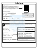
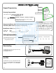
PRINTER Hold the printer’s tab perpendicular to the Lock’s infrared LED as shown in Figure 1 and Figure 2. If the printer Infrared LED Printer Tab Infrared LED 123 Printer Tab 456 789 :0; DL3000 to Printer - Side View DL3000 to Printer - Front View Figure 1 55. Print Audit Trail Figure 2 ;55: Hold the printer over the lock's infrared sensor as shown in Figure 1 and Figure 2. 20 events will print at a time; press 1 for more events, or 9 to quit.
AL-DTM 59. AL-DTM Door Number ;59 ; [__]: Door Number) • Door Number must be between 1- 48. 4 For use with Alarm Lock’s AL-DTM Data Transfer Module. Using the AL-DTM up to 48 locks can be Downloaded/Uploaded and History LOGs can be retrieved. Enter a door number for each lock. After configuring the AL-DTM, using Alarm Lock's DL-WINDOWS Software, any of the following data transfers can be initiated by plugging the AL-DTM into the lock and simply entering User Code 299 at the lock.
RELAY ;67 67. Add Relay Function ; [_]: (Relay Function) • Relay function must be 1-11 4 Program 1 or more functions below to activate the Relay for 2 seconds when the following event occur: 1. 2. 3. 4. Remote Input while enabled Remote Input while disabled Failed Entry attempt Disabled user entered code 6. 7. 8. 9. Function 90 Activated Locked by Schedule Unlocked by Schedule Keypad Lock Out 68. Delete All Relay Functions 11.
SCHEDULES NOTE: Clear All Schedule and Timeout Functions by entering Function 12. Scheduled Group Enable/Disable Use the functions below to Enable/Disable Groups at the time programmed. • For day enter: 1 for Sunday, 2 for Monday, 3 for Tuesday, 4 for Wednesday, 5 for Thursday, 6 for Friday and 7 for Saturday, 8 for Monday to Friday, 9 for Saturday and Sunday, 0 for all days of week. 74. Schedule Enable Group 1 ;74 3 ;[_] (Day) 75. Schedule Enable Group 2 ;75 ;[_] (Day) 76.
QUICK SCHEDULES Quick Schedules - Enable Group • Group number must be 1-4 Enter the number of the group that is to be enabled for the time specified for the Quick Schedules below: 84. Business Quick Schedule ;84 3 ;[_]: (Group) 7AM-5PM, Monday - Friday 85. Day Quick Schedule ;85 ;[_]: (Group) 7AM-5PM, All days 86. Evening Quick Schedule ;86 ;[_]: ;87 ;[_]: 3PM-1AM, All days 87.
SCHEDULES GROUP 1 ACTIVATED Scheduled Relay Activation (Group 1 Activated) • Also program Relay Function 6 using Function 67 (; 6 7 ; 6 :). • For day enter: 1 for Sunday, 2 for Monday, 3 for Tuesday, 4 for Wednesday, 5 for Thursday, 6 for Friday and 7 for Saturday, 8 for Monday to Friday, 9 for Saturday and Sunday, 0 for all days of week. • Enter time of day in 24 hour format.
Note: Advanced User Programming Add a User that is a member of Group 2 & Group 3 Program a User Code of 789 that is a member of Group 2. Refer to Function 2 (page 11). Use Function 2, and add the new user as User 101 (Users 101-150 are members of Group 2): Add User 101: ;2 ;101 ;789: Make User 101 also member of Group 3 using Function 35: ;35 ;101 ;23: Note: Although User 101 is by default a member of Group 2, Group 2 must be included when using Function 35 or the Group 2 association will be removed.
Default Values are shown in parentheses.
User Number (1-300) User Code (3-6 digits) Group Association 1 2 3 Program Set Ability 4 1 Note: For a complete list of user codes obtain a print out from either the remote printer (Program Function 56) or using the DL-3000 WINDOWS Downloading Software.
Day(s) Function Number Up to 150 scheduled functions can be programmed.
ALARM LOCK LIMITED WARRANTY ALARM LOCK SYSTEMS, INC. (ALARM LOCK) warrants its products to be free from manufacturing defects in materials and workmanship for twelve months following the date of manufacture. ALARM LOCK will, within said period, at its option, repair or replace any product failing to operate correctly without charge to the original purchaser or user.