
Service manual


LED Fusing Considerations
Although the average current draw per module is very low, due to the type of circuit used to power each module, the instanta-
neous peak current to a module can be signicantly higher during low voltage conditions. To avoid prematurely blowing ATO style
fuses or tripping breakers it is recommended the following rule-of-thumb be used to size fuses or breakers. This is especially
important in lightbars with many LED modules running off a single fused source.
Minimum fuse size calculation: (See Wiring Diagram page 5)
For LED 12 volt electrical current only
.5 X (number of 3 LED modules being fused) = Total Electrical Current at 12.8 VDC
9
Troubleshooting
All SuperVisorTLs are thoroughly tested prior to shipment. However, should you encounter a problem during installation or during the
life of the product, follow the guide below for information on repair and troubleshooting. Additional information may be obtained from
the factory technical help line at 314-996-2800. Follow the guide below for information on repair and troubleshooting.
TROUBLESHOOTING GUIDE
Note: LED modules must be replaced as a module. There are no user serviceable parts.
PROBLEM
LED module not
operating when
powered.
QUESTIONS POSSIBLE CAUSE
a. Bad power/ground
connection.
b. Defective module.
SOLUTION
a. Fix connection.
b. Replace module
N/A
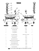
Torus 3LED PCB
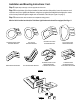
Changing Flash Patterns
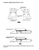
To change the ash patterns on the LED Light Heads, remove the mounting screws that attach the SuperVisor's Cover to the
Outer Panel to gain access to the printed circuit boards inside (see the exploded view on page 10). Momentarily short and
release the pattern change prongs as shown below to change patterns. Carefully replace the SuperVisor's Cover over the
Outer Panel and replace the Cover Mounting Screws.
Note: Be extremely careful to replace the wiring such that you don't pinch a wire when you replace the
SuperVisor's Cover. Test the unit to be sure that it works properly.
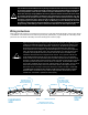
This Product contains high intensity LED devices. To prevent eye damage,
DO NOT stare into light beam at close range.
WARNING!
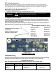
JP1
Flash Pattern Header for Torus
1. Momentarily short and release to
change patterns
2. Hold for 5 seconds to reset the
ash pattern to the rst pattern
Directional Module Flash Pattern - Table 2
Cycle Flash-70 - (DEFAULT) Variable Flash Single
NFPA Quad Flash-80 Cycle Flash-150
Quad Flash-70 Five Flash-150
Steady Burn Quad Flash-150
Five Flash-70 Triple Flash-150
Triple Flash-70 Double Flash-150
Double Flash-70 Single Flash-150
Single Flash-70 Single Flash-250
Quad Pop Flash-70 Single Flash-375
Triple Pop Flash-70