INSTALLATION & OPERATION MANUAL SUPERVISOR™ SuperVisor™ Interior Lighting System CHEVROLET IMPALA CONTENTS: Introduction .......................................................................... 2 Unpacking & Pre-Installation ............................................... 3 Installation & Mounting ..................................................... 3-7 Wiring Diagram & Instructions .......................................... 8-9 Fusing and MR8 Lamp Installation ....................................
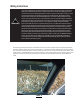
Introduction The SuperVisor™ is an interior lighting system that fits in the visor area near the top of the windshield. It delivers an amazing warning signal, including MR8 powered takedown lights. The SuperVisor is designed on a modular basis, which means that the light bar can be customized to meet most any requirements. The SuperVisor has room for up to eight LED lightheads plus two MR8 takedowns. Each lighthead is individually wired for any flash pattern or combination of flash patterns required.
Unpacking & Pre-installation Carefully remove the SuperVisor™ and place it on a flat surface, taking care not to scratch the lenses or damage the cable coming out of the side. Examine the unit for transit damage, broken lamps, etc. Report any damage to the carrier and keep the shipping carton. Standard light bars are built to operate on 12 volt D.C. negative ground (earth) vehicles. If you have an electrical system other than 12 volt D.C.
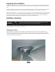
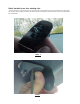
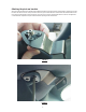
Attach brackets to sun visor retaining clips In order to remove the sun visor retaining clip, unscrew the one torx screw holding it in place. Place the inner bracket on the retaining clip as shown in Figure 2. Attach the inner bracket and retaining clip to the headliner as illustrated in Figure 3. Do not completely tighten the screw at this time.
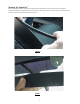
Attaching the pivot arm brackets Attach the outer brackets that are supplied noting the difference between passenger and driver side brackets. Position the driver's side bracket on the driver's side sun visor's pivot arm as shown in Figure 4. Attach the driver's side bracket to the headliner with the inner torx screw as shown in figure 5. Next, move the sun visor over to gain access to install the other two torx screws. Do not tighten the screws at this time.
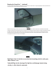
Mounting the SuperVisor™ Before mounting the SuperVisor, apply gasket stripping to the front edge of the lower chassis in order to prevent scratching the windshield. See Figure 6. Once all four brackets and sun visors are attached, the SuperVisor is now ready to be installed. Position the SuperVisor in the center of the windshield as shown in Figure 7.
Mounting the SuperVisor™ (continued) The two center brackets should line up with the holes in the SuperVisor's lower chassis. Using the supplied 1/4"-20 bolts and the internal tooth lock washers, loosely install them as shown in Figure 8. FIGURE 8 Next, if necessary, slightly loosen the three pivot arm bracket retaining screws in order to align the pivot arm bracket's hole with the mating chassis hole on the end of the SuperVisor.
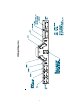
Wiring Diagram
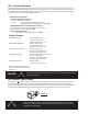
Wiring Instructions ! WARNING! Larger wires and tight connections will provide longer service life for components. For high current wires it is highly recommended that terminal blocks or soldered connections be used with shrink tubing to protect the connections. Do not use insulation displacement connectors (e.g. 3M® Scotchlock type connectors). Route wiring using grommets and sealant when passing through compartment walls. Minimize the number of splices to reduce voltage drop.
LED Fusing Considerations Although the average current draw per module is very low, due to the type of circuit used to power each module, the instantaneous peak current to a module can be significantly higher during low voltage conditions. To avoid prematurely blowing ATO style fuses or tripping breakers it is recommended the following rule-of-thumb be used to size fuses or breakers.
Directional module Flash Pattern - Table 2 CycleFlash (DEFAULT) NFPA QuadFlash75 Steadyburn ModelFlash ActiveFlash FiveFlash70 QuadFlash70 TripleFlash70 DoubleFlash70 SingleFlash75 Quad Pop Flash75 Triple Pop Flash75 SingleFlash375 SingleFlash250 SingleFlash150 FiveFlash150 QuadFlash150 DoubleFlash150 TripleFlash150 Momentarily short and release to change patterns J1 Flash Pattern Header for OPTIX/LEDX Troubleshooting All SuperVisors are thoroughly tested prior to shipment.
Parts List Reference Number Part Description Part Number 1 +12V Cooling Fan T05612 2 *LEDX LED Module *Contact Code 3, Inc for P/N 3 MR8 lamp T09600 4 Chassis T09614 5 Outer Panel S51410 6 *Optix LED Module *Contact Code 3, Inc for P/N Not Shown Inner Mtg. Brkt. Impala T09615 Not Shown Outer Mtg. Brkt. Impala Pass. T09617 Not Shown Outer Mtg. Brkt. Impala Dr.
Notes 13
Notes 14
Notes 15
WARRANTY Code 3, Inc.'s emergency devices are tested and found to be operational at the time of manufacture. Provided they are installed and operated in accordance with manufacturer's recommendations, Code 3, Inc. guarantees all parts and components except the lamps to a period of 1 year, LED Lighthead modules to a period of 5 years (unless otherwise expressed) from the date of purchase or delivery, whichever is later.