
User Manual

4. Device Description
The Power module 2002 POW is designed as plug-in module for the RF reader modules 1plus, 2plus and 4plus.
The terminal layout for the pins 1 to 8 is congruent to the layout of the reader modules and can be connected with pin
connectors (2,54mm grid).
The pins 10 to 19 are designed for 3,5 mm screw connectors.
Also available on the power module are a push button (connected to pin 2 of the reader modules) and a relay (con-
nected to pin 3 of the reader modules open collector output). A LED is switched in parallel to the relay.
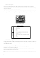
PCB Power module 2002 POW
Terminal positions:
1 … +5V
2 … input push button
3 … output open collector (max. 200 mA)
4 … output data, TX-TTL
5 … input data, RX-TTL
6 … GND
7 … Antenna 1
8 … Antenna 2
10 … 12V=/~ (e.g. transfomer or external plug-in power supply)
11 … 12V=/~ (e.g. transfomer or external plug-in power supply)
12 … relay switch normally open
13 … relay center
14 … relay switch normally closed
15 … output data TX (RS 232 or TTL – depending on RF reader module)
16 … input data RX (RS 232 or TTL – depending on RF reader module)
17 … GND
18 … antenna 2
19 … antenna 1
Connectors to the
reader modules
External connectors
power module
(for screw connectors 3,5 mm)
5. Functional Description
The power module provides a stabilized 5 V supply voltage for the RF reader modules. It comprises a rectifier and a
voltage regulator.
One can apply both a 9V AC or a 12 V DC source to the pins 10 an 11 of the power module. The power module is pro-
tected against wrong polarity.
6. Connections and Putting into Oeration
The exact terminal positions can be seen in the table in Section 4. Device Description above.
The contacts 1 to 8 are designed in a 2,54mm grid.
Pin connectors can be used for soldering the power module and the RF reader module to a sandwich assembly.
Take care of sufficient distance between the two pcbs.
Before putting into operation of the pcb assembly please refer to the user guide of the corresponding RF reader mod-
ule.
4